In my small living room where my front mains have to live in the corners, I’ve been thinking about employing horns or a ~5”~6” coaxial as horns seem to require a seasoned designer. I believe (not sure) I want to tighten up the dispersion as low as possible from a maximum 7” diameter.
Being so close to the walls and right by the loveseat makes me think I want to attenuate as much off axis response as I can from mentioned size. Diffusers and absorption are not an option considering the size needed to perform a wideband treatment of the first reflections. If a wideband treatment isn’t employed then the image suffers in a different way, again, I believe.
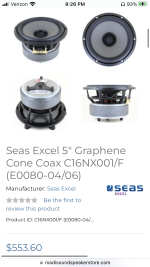
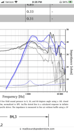
I’ve looked at many coaxial drivers thinking that the tweeter would be horn loaded by the cone but just about every response graph looks super ragged compared to the separate component drivers I usually would consider. I must be missing something here. For instance, I see tweeters having a recommended high pass of like 3.5khz in the middle of a 6” or 7” woofer. So the woofer looks to be breaking up in or around the filter as well as beaming. Some high end coaxials seem to be designed in this way, does it all come together in a well behaved power response that the raw graphs don’t demonstrate?
The listening space I’m trying to make the most out of. There’s a few inches of wiggle room with the lamp/shelves but not a whole lot. I’m already planning on building short stands to raise the bookshelve speakers to where the woofer and especially the higher frequencies are as minimally obstructed as possible by the loveseat. I wouldn’t mind a nice coaxial mounted high enough to completely clear the armrest.


Am I thinking along the right path about horns or coaxials to control directivity? Here’s examples of what confuses me.


I’m not shopping in this range but it’s a good example that what I think I’m seeing is across the board in price with coincident style drivers.
Being so close to the walls and right by the loveseat makes me think I want to attenuate as much off axis response as I can from mentioned size. Diffusers and absorption are not an option considering the size needed to perform a wideband treatment of the first reflections. If a wideband treatment isn’t employed then the image suffers in a different way, again, I believe.
I’ve looked at many coaxial drivers thinking that the tweeter would be horn loaded by the cone but just about every response graph looks super ragged compared to the separate component drivers I usually would consider. I must be missing something here. For instance, I see tweeters having a recommended high pass of like 3.5khz in the middle of a 6” or 7” woofer. So the woofer looks to be breaking up in or around the filter as well as beaming. Some high end coaxials seem to be designed in this way, does it all come together in a well behaved power response that the raw graphs don’t demonstrate?
The listening space I’m trying to make the most out of. There’s a few inches of wiggle room with the lamp/shelves but not a whole lot. I’m already planning on building short stands to raise the bookshelve speakers to where the woofer and especially the higher frequencies are as minimally obstructed as possible by the loveseat. I wouldn’t mind a nice coaxial mounted high enough to completely clear the armrest.
Am I thinking along the right path about horns or coaxials to control directivity? Here’s examples of what confuses me.
I’m not shopping in this range but it’s a good example that what I think I’m seeing is across the board in price with coincident style drivers.
Attachments
Last edited:
Another option I’m considering is building small satellite cabinets with a Dayton Rs100 and neo tweet, possibly ring radiator on the top shelf there. The Rs100’s should naturally roll off starting around the low 100’s being corner loaded and then I could have a small subwoofe on each bottom shelf which should also benefit some of the small room bass issues.
To a degree it does. While coaxes have their foibles, they should be easy to deal with. You want to choose the right crossover frequency, you don't have a lot of choice there. In theory they will perform consistently but if not, you don't have a lot of choice there either.does it all come together in a well behaved power response that the raw graphs don’t demonstrate?
Crossing them should be easy, since getting them in phase is an appropriate goal, and the response requirements are closer to the obvious than for a conventional two-way.

I understand that the dsp amplifier boards have their shortcomings, I have a bucket full and basically every separate transducer in my system is/will be fully active. Does my ability to tune with dsp reasonably well make a coincident driver something for me to take more seriously?
If I dig deep enough should I be able to find information on how the power response of a 6”-7” coax generally might look?
If I dig deep enough should I be able to find information on how the power response of a 6”-7” coax generally might look?
The benefit of the coax is you can get better results without knowing much about the power. If you get a coax, put it in a nice rounded box, cross it in the simplest proper way and then listen and EQ... you'll probably be OK. You wouldn't use as simple a procedure with a typical two-way.
DSP itself doesn't have anything to do with it since it doesn't change what it's possible to achieve in a typical crossover such as this.. however you may possibly find it easier.
DSP itself doesn't have anything to do with it since it doesn't change what it's possible to achieve in a typical crossover such as this.. however you may possibly find it easier.
A simple rising DI from the woofer pistonic region up to the angle of the waveguide... in theory.should I be able to find information on how the power response of a 6”-7” coax generally might look?
Corners are challenging. You can get very good results but you must do it a certain way.
Since your waveguiding will be greater than 90 degrees set by the cone, you'll want to be out from the corners. You could waveguide that angle down to a very low frequency using a baffle, though you may end up wanting to treat the walls in compromise once you see what's involved. However, you could also do a cardioid.. but you might want to cross to a woofer for that.
Since your waveguiding will be greater than 90 degrees set by the cone, you'll want to be out from the corners. You could waveguide that angle down to a very low frequency using a baffle, though you may end up wanting to treat the walls in compromise once you see what's involved. However, you could also do a cardioid.. but you might want to cross to a woofer for that.
I’ve always been interested in this 8” waveguide from our friends at diy sound group. While horn design appears complex, it seems like the actual horn geometry is very complex. On the other hand, after a properly functioning horn has been produced I see evidence that a very basic guideline is to roughly match the width of the driver and horn to achieve a mostly consistent power response, with the right x-over point.
Does an 8” horn behave similarly to an 8” cone driver? As I recall it’s length of the wavelength or quarter wave in relation to the cone that heavily influences the dispersion in both cases. The edges of this 8” horn aren’t rolled back so it would seem that it has an effective mouth closer to 7.5” or so.
I also wonder how a small full range would work in this waveguide. Erin h measured the Tectonic bmr 2” with surprising results, this smaller version may perform well also.
The horn description states to high pass no lower than 1,000hz. Do we get destructive standing waves sub 1,000hz or does the horns effect become moot?
I’m a little weary about crossing in the meat and potatoes of the vocal range, especially not being an expert on the subject. If a horn just ceases to control directivity then it will be very tempting to try a small bmr in a waveguide. But then again I could choose a large format tweeter, cross around 2k and be fine. I realize that with a coherent crossover one can generally have said crossover nearly anywhere.
Is it ok to say that the Dayton Epique 7” and this 8” waveguide roughly should work together? Possibly the Epique 5.5” as it behaves much better and in a box large enough to hold an 8” waveguide, it could be ported/pr to play quite low. The 7” driver shows a compliance limited xmax around 11mm where the 5.5” behaves nicely to almost 16mm, if I’m understanding the data.
I have a pair these Dayton .5cf cabinets new on the shelf that would probably be perfect for the 7” Epique sealed and the 8” horn while looking nice and saving time on cabinet fabrication. I really like them in my shop with the Anarchy 704, Dayton reference 8” pr, and Tectonic 2”. Running active I could tune a 8” horn to a 7” woofer if the geometry allows.
Attachments
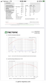
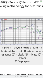
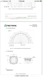
The Epique graphs above are from audio express, they’re the only ones I’ve found that show the actual dispersion in the lower frequencies. All of the other graphs seem to normalize the response below 1khz-2khz making drivers appear to have perfect 180* radiation up to around beaming. With what appears to be true dispersion data I feel more confident in trying to match a horn and woofer. For example, the Dayton graph shows a perfect 180* dispersion up to 2khz…

One last thing for now, it looks like horns can attenuate the highest frequencies, would something like a ring radiator help upper extension?
Not exactly. What you've read there is a kind of average for a more typical waveguide (not horns in general). For waveguides larger works too, but smaller becomes a problem. Use the smallest dimension (vertical) as a guide.Does an 8” horn behave similarly to an 8” cone driver?
I’d like to narrow the horizontal dispersion most but the floor and ceiling are probably problematic as well.
Or you asking for something more in depth? I only think that I want a smoothly tightening response starting as low as possible while remaining consistent with the woofer.What directivity pattern do you seek?
//
Well, I reacted to "Am I thinking along the right path about horns or coaxials to control directivity?" and thought you had a more specific goal as you want to "control directivity"? Just curious...
//
//
A lot of this is related to throat/cone discontinuities and woofer surround effects. There are multiple reflection points in the geometry that wouldn't be there in a normal horn or waveguide. This tends to look worse on graphs than it sounds. If you look at the KEF LS50, all the stuff that looks kind of strange compared to a normal woofer and tweeter is there to smooth geometry and improve the response flatness. Without a nearly flat surround and additional waveguide elements, it's hard to get the raw response flat in a coaxial. Though even in the ragged ones some do a better job of it than others.just about every response graph looks super ragged compared to the separate component drivers
So I’ve mistaken waveguides and horns as one and the same. I’m guessing that the diy sound group is a waveguide and 8” waveguide over a 5.5” to 7” woofer is ok if I can reasonably match the dispersion characteristics?Not exactly. What you've read there is a kind of average for a more typical waveguide (not horns in general). For waveguides larger works too, but smaller becomes a problem. Use the smallest dimension (vertical) as a guide.
What would be y’all’s choice in my situation? An ~8” waveguide over a mid sized woofer or 5”-6” coaxial sealed like this, and a small subwoofer under each side? Considering that the drivers have to be in the corner, am I correct in thinking that if I can achieve a narrowing response around 2khz and above it would be pretty decent? My thoughts are that around 2khz the quarter wavelength is about the distance from the wall if the speaker is right against the wall. This would in essence make the wall a kind of continuance of the waveguide on one side, and while diffusing the image slightly by making the radiating surface slightly larger, it would remove a lot of the first reflection?


Are there any other suggestions that I’m not asking about to help corner imagining? I could install a 2” thick or so absorbing panel behind the shelf, either only behind a coax/fullrange bookshelf or a 2”x12”x36” absorber behind the whole shelf to help a little as a bass trap? I really appreciate everyone’s time and input here. I’ve put a decent amount of time and money into my diy av receiver with dsp capabilities so I really want to get the best out of the most important parts, the speakers.
Are there any other suggestions that I’m not asking about to help corner imagining? I could install a 2” thick or so absorbing panel behind the shelf, either only behind a coax/fullrange bookshelf or a 2”x12”x36” absorber behind the whole shelf to help a little as a bass trap? I really appreciate everyone’s time and input here. I’ve put a decent amount of time and money into my diy av receiver with dsp capabilities so I really want to get the best out of the most important parts, the speakers.
The absorber idea is interesting, but I'm thinking of it in a different way. To do much of anything in the bass, you have to have a ton of thickness, so that's not really relevant.
But even 1 inch of acoustic foam absorbs well from 500 Hz and up. If you extend the absorber out around your speakers, I think you could absorb a good amount of the first reflection energy. Kind of like a mini Live-End Dead-End setup.
https://acousticalsolutions.com/product/alphasorb-fabric-wrapped-acoustic-panel/
- Home
- Loudspeakers
- Full Range
- Making sense of coaxial response