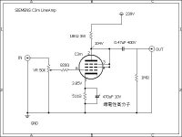
It is simply a triode wired pentode hooked up as a voltage amplifier.If it works, how much would I get at op
Provided the load impedance at the OP connexion the gain will be ~0.75 0f the tube triode mu.
OP should drive into>50K.🙂

The data sheet (http://frank.yueksel.org/sheets/190/c/C3m.pdf) says the tube has a mu of 18 when triode strapped. With the resistive anode load you'll get less than mu as the amplification factor, but I'd still expect the amp to have a gain of around 10 V/V (20 dB). That's quite a bit for a line stage but one could lower it by removing the cathode bypass cap.
I suggest getting yourself a copy of Morgan Jones' book: Valve Amplifiers. It has all the information you need to analyze the circuit.
Tom
I suggest getting yourself a copy of Morgan Jones' book: Valve Amplifiers. It has all the information you need to analyze the circuit.
Tom
Or grab one of Tubelab's boards before he closes up shop at the end of the year: www.tubelab.com
Tom
Tom
I'm not sure, that for -tube- novice the C3m is good start.
It's the 20V filament, special (loctal) base tube. Both of tube and socket are expensive.
As tomchr wrote, the trioded tube's gain is too high for -simple- line stage (practically x17 if CCS loaded).
I usually use trioded C3m (and 6.3V filament C3o or C3g) as VAS stage for amplifiers.
p.s.
Theoretically it's working, but gain and distortion not optimal.
Last edited:
Then go do that... 🙂 I still recommend reading Jones' book, though.OP, a tube noob, wants to build his first audio valve amplifier with this scheme 😊
Tom
Luckly I was able to secure an SPP and TSE-II board. The boards quality is amazing. George has been at the cutting edge of tube amp development for so long is not even funny, I am ashamed to say I became aware of tubelab.com only recently as I started to getting interested in horns and tubes. It's a shame he's getting out of the business.Or grab one of Tubelab's boards before he closes up shop at the end of the year: www.tubelab.com
Tom
Anything you can suggest to optimise this scheme, or any favourable single tube amp to get similar output, which is quite enough I see, using this valve in driver stage has plenty of schemes available, but I want to stick to one valve amp as a first timerTheoretically it's working, but gain and distortion not optimal.
I'm reading Briggs and Garner's awesome book, but completing entire tube theory would take few more years! Theory is the justification, making is the necessity 😊Then go do that... 🙂 I still recommend reading Jones' book, though.
Tom
You picked the C3M pentode, it is not going to be any simpler than your schematic . . .
unless you use a triode (2 less pins to connect to).
How well that circuit works for you depends on the maximum output signal voltage you need, versus the distortion at that output voltage.
Getting the circuit up and working will be an eduction, whether or not you have any difficulty making it work as expected.
Solder connections, electrolytic polarity, resistor values as in the schematic, working tube, wiring dress to avoid making an oscillator, etc.
Be careful, that 0.47uF output capacitor and 1Meg resistor has a very long time constant of 0.47 seconds.
If you have 239V B+ and a cold filament C3M, the voltage on the output terminal will be 239V, and 0.47 seconds later will be 86.4V,
and after 5 x 0.47 seconds will be a very low voltage.
Each 0.47 seconds, the remaining voltage is decreased to 37% of the former voltage.
If you never build, tinker, etc., no matter how good the text books are, you will be missing something.
I started with the 1956 ARRL Radio Amateur's Handbook.
Be very careful of the high voltage. Be sure to use a bleeder in your power supply.
Safety First!
Prevent the "Surviving Spouse Syndrome"
Have fun!
Well, the pentode shown was recommended by one who's listening valves for years, using it in driver stage, to drive 300b, I just put single tube amp and the tube name in search, I did search with well known valves, with same single tube amp as operator in search, which yielded much more complex things, which I won't be able to make in my lifetime, I know my limitations 😊
The complex schemes are heavy in transformers, interstage or output, which is certainly is a put off for this minimalist, so I chose this as a go, even though it has a capacitor at output which is against my liking, as my current own made amp has none there 😁
Those unknown artsy characters shown in the scheme made me skeptic about the scheme so I put this here for a definitive discussion 😊
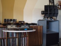
About a month ago, I brought a CD player with XLR balanced outputs, and a pair of mono-block balanced amplifiers that I designed and built.
At the dual-club meeting, It was well received, and I got many comments about the good sound.
Of course, the secret was in the excellent loudspeakers.
They are a great design, plus they are very efficient. So my very low power mono-block amplifiers were able to provide adequate sound levels.
Now, for the dirty little secret . . .
There was an RC coupling from each driver tube to its output tube. (Horrors! Worse than a Halloween Movie).
Capacitors: 3 in the B+ filtering, and 1 each in the RC driver to output tube coupling (balanced, so 2 coupling caps per mono-block).
Nobody commented about the bad sound from those 5 capacitors. I guess they were not really listeining.
To be honest, I Was criticized for using only 0.1uF RC for the coupling caps, that had a -3dB low frequency @ 16Hz, and -1dB @ 32 Hz.
It was recommended to use at least 0.2uF or 0.22uF.
If and when I get around to it, I will change those 0.1uF capacitors, and use 0.22uF.
By now, you probably know that I do not have anything against using capacitors where it makes sense. In the hands of a designer (in the circuit)
they can be great problem solvers. Just do not hold a charged capacitor in your hands.
A picture is attached showing my 2 balanced mono-block amplifiers (the ones up front with the small meters); Marantz CD player with balanced XLR outputs in front of the mono-blocks; and one of those two Wonderful 3-Way loudspeaker systems.
Attachments
Last edited:
A one valve amp direct into a speaker is possible, several variants were often built in the 1940s & 1950s,but I want to stick to one valve amp as a first timer
They use an all-in-one tube such as a 117L7GT, a pentode of short grid base & included rectifier.
And driven by a shellac disc driven crystal pickup, good enough to satisfy a market for a very low cost record player.
Not exactly hifi or much else.
There are several single tube amps on the web using triode / pentode tubes in one glass bottle.
That is probably the best way forward at this stage of your understanding of the art. 🙂
- Home
- Amplifiers
- Tubes / Valves
- First valve amp