I have a GT-42 that both FR and RR channels are about 1/2 the output of the FL and RL channels. This seems to be a problem with these amps but I have not found someone come back and say how or if they fixed it. https://www.diyaudio.com/community/threads/boston-gt-40.370270/
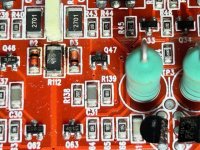
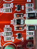
The amp had a burnt/open 4R70 resistor R112 on channel FL. The board was burned under it and one pad has lifted although it is still connect to the trace going under the 100 nF polyester film capacitor. Output fet drain-->100nF cap-->R112-->secondary ground/non-bridging speaker terminal. I now have 7- 1/4w 33R resistors paralleled off the board for 4R7, for testing.
The amp had no output on any channels and about 500 mVdc across the speaker terminals. I found the negative regulated supply was not being produced for the op-amps and found a loose connection on the BC53, Q85, fixed that.
Now I have no DC across speaker terminals and I have audio on all 4 channels. Problem is both right channels front and rear have 1/2 the output (4 Vpp) of both left channels front and rear (8 Vpp) with 100 Hz sine wave. I have the same magnitude of the signal on the input side of the 1 uF caps C38, C42, C46, C50, but different outputs, relative to front and rear, on the 5532s within the output side.
Both gains turned full ccw, least sensitive. I have tried multiple switch positions, switching inputs L or R and L & R, different sources.
Of course a schematic would be great. I have the one for the GT-28 in the previous thread I linked to and also downloaded some STEG schematics, but they are to dissimilar.
I can take more/different pictures if necessary. The discoloration in the picture of the regulated voltage section is not there that is a reflection I guess.
Any help would be appreciated.
Attachments
-
 Open Burnt Resistor.jpg120.5 KB · Views: 158
 -
 Burnt Board Pad Lifted.jpg74.5 KB · Views: 150
 -
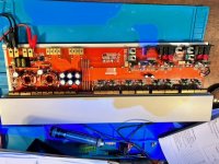 GT-42.jpg72.4 KB · Views: 212
 -
 1 Channel.jpg78.6 KB · Views: 151
 -
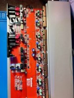 Front End and Output.jpg72.9 KB · Views: 160
 -
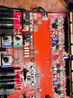 Front End and 2 Output Channels.jpg737.2 KB · Views: 183
 -
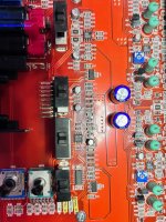 Regulated Voltage.jpg657.7 KB · Views: 153
 -
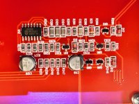 LM339.jpg414.7 KB · Views: 149
Do you see a perfectly clean ground (no signal) on all of the positive inputs (pin 3 of U1 and U2) of all channels?
Referring to the GT-28 designations.
Referring to the GT-28 designations.
Last edited:
Did you confirm that the 1uF caps were within tolerance? The input and output should be the same, especially if driving 10k ohms.
U1, U2, U3, U4, pin 3:
Referenced to non-bridging speaker terminal, No signal.
-0.0002 Vdc
2.01 mVac @ 39.3 kHz
FYI, U2 and U4 are associated with the channels that halve half the output.
Referenced to non-bridging speaker terminal, No signal.
-0.0002 Vdc
2.01 mVac @ 39.3 kHz
FYI, U2 and U4 are associated with the channels that halve half the output.
They were all within the 20%, but the two on the lower output channels were on the low end at 0.805 uF. All of them looked like some electrolyte may have leaked out. Although they didn't smell bad when I desoldered them it was a little crusty greenish brown under them.
I will have to order some 1 uF 50V replacements. I've got to order the 4R7 resistor R112 also. Do you think it is worth soldering to that lifted pad on R112?
I did see in the notes on the boston GT-40 you added the through hole capacitors. I thought those caps might be the culprit but since the difference from good channel to bad channel was exactly the same on both pair of channels I was trying to find something in common between the two rear channels.
Did you try installing the capacitors from the normal channels into the low channels (and vice-versa) to see if the low volume followed the capacitors?
You need to scrape away all of the carbonized circuit board from under R112.
Did the corresponding resistors in the other channels also run as hot? Did you desolder those other resistors to examine the board under the resistors?
You need to scrape away all of the carbonized circuit board from under R112.
Did the corresponding resistors in the other channels also run as hot? Did you desolder those other resistors to examine the board under the resistors?
They were not in very good condition to resolder back on after removal.
I did check if the burned board was conductive and all was good, but I will scrape it away to make sure.
Those other 4R7 resistors all seem fine, no evidence the were hot although I did not remove them to look under them. The one that did get hot must have gotten really hot, it melted the case of the capacitor next to it. I'm not sure what would of caused it to get so hot. None of the others are heating at all when the amp was running.
If that 4.7 ohm resistor and the capacitor are in series, they are likely the Zobel network and will overheat if the channel is abused or the channel oscillates, for some reason.
To prevent damaging the pads when removing the SMD electrolytics, heating the board from the bottom helps significantly. Either the hot-air rework station or the 1157 lamp heater (shown on the 'Alternate Solder Methods' page) work. I prefer the lamp because you can apply heat hands free and you can see where the heat is being applied (unless you have a 3 or more layer board).
To prevent damaging the pads when removing the SMD electrolytics, heating the board from the bottom helps significantly. Either the hot-air rework station or the 1157 lamp heater (shown on the 'Alternate Solder Methods' page) work. I prefer the lamp because you can apply heat hands free and you can see where the heat is being applied (unless you have a 3 or more layer board).
They are in series.
On the 4.7 ohm resistors they are smd size 2010. Mouser and DigiKey have that size in 3/4 and 1 watt. They are calling the 1 watt resistor a pulse resistor. I don't know what the originals power rating are, would you order the 1 watt?
Okay, I appreciate it.
I will order some parts this evening and get back to it when they get here in a couple of days. I was just digging through some old pcbs that I kept for spare parts hoping I could scavenge some caps and resistors, but no luck.
The are likely the same but if some are rated for 1w order them. In a different GT Trading amp, they are listed as 1W. As long as they fit, order the higher rated resistor.
If you're concerned about the resistor pad, there are multiple options. The neatest and easiest may be to order a new cap, install the new cap but wrap a piece of small wire (1/4w resistor leg) around the lead that goes to the resistor and solder that wire to the loose resistor pad (as well to the capacitor lead before installing it).
If you're concerned about the resistor pad, there are multiple options. The neatest and easiest may be to order a new cap, install the new cap but wrap a piece of small wire (1/4w resistor leg) around the lead that goes to the resistor and solder that wire to the loose resistor pad (as well to the capacitor lead before installing it).
Replacing the four 1uF 50V caps C38, C42, C46 and C50 fixed it.
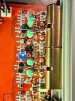
When I got the amp all the bias pots were turned full CCW, the amp draws ~1.2 amps at idle. Everything I could find on the various GT Trading amps said between 350 mA to 750 mA bias current per channel depending on the model. The GT-28 schematic said 500 mA. So that is what I set them at.
With the pots turned all the way CCW the sine wave looked fine. Is there a possibility it was this way from the factory? There is some evidence that someone has worked on this amp before.
Did you look at a 20k sine wave (low level, only about a volt or so at the speaker terminals) while driving a load?
First, my function generator control knob has steps instead of being smooth, so I can get the voltage to 0.95 Vac or 1.10 Vac across the speaker terminals.
Gains set full CCW. Bias set at 500 mA/Ch.
All channels look good at 0.95 Vac. One channel just starts to clip the top of the 20 kHz sine wave at 1.10 Vac, but the other three look good and clear.
These were into 2 ohm dummy loads.
Gains set full CCW. Bias set at 500 mA/Ch.
All channels look good at 0.95 Vac. One channel just starts to clip the top of the 20 kHz sine wave at 1.10 Vac, but the other three look good and clear.
These were into 2 ohm dummy loads.
Is the clipping channel clean at lower frequencies and higher levels (up to clipping at the rails)?
Does the signal at the 1uF cap look clean where the output starts to clip at 20k?
If you increase the bias slightly, does the clipping go away?
If you increase the bias slightly, does the clipping go away?
Increasing the bias slightly does make the clipping go away.
I will check the 1 uF cap in a little bit.
I turned the bias full CCW to see and the 20 kHz signal is quite distorted, so I guess they do need to be biased at about 500 mA.
When the bias was set until all signals were clean, I unhooked the input and checked the DC voltage across the source resistors and they were all over the place. They ranged from .5 mV and a couple were as high as 25 mV.
Are all of the 0.1 ohm source resistors within tolerance?
Are all of the parallel output FETs matched?
How many FETs per channel?
Are all of the parallel output FETs matched?
How many FETs per channel?
In the board they test between .08 and .13, but the majority read 0.11 ohm, they are 0.1 ohm 5%, so none of them are in tolerance, 0.095 to 0.105 ohms. With my meter in relative mode, the best I could get between the leads was +/- 0.01 ohms fluctuating, so that may be contributing. The resistors are hard to get to because they are standing up and they put the bottom of them tightly against the pcb. Should I pull one leg from the board on each of the 16 resistors?
The output FETs look original.
2 pcs FQP33N10s and 2 pcs FQP22P10s per channel.
The output FETs look original.
2 pcs FQP33N10s and 2 pcs FQP22P10s per channel.
- Home
- General Interest
- Car Audio
- Boston Acoustics GT-42 R and L Channel Outputs Uneven