I want to make an in-line high-pass filter, but before I order my parts, I just wanted to make sure, it really is just the R and the C, right? There are no extra pieces that should be included for a real filter that don't exist in the educational diagrams?
One R and one C gives you a 6dB/Octave slope. This is fine where some low frequency signal can be tolerated, such as a sub-sonic filter, but it is not great for sensitive tweeters or horns. Passive RC filters usually use a 10x impedance per stage to avoid loading the previous stage. This is fine when you start with a low speaker impedance and drive a high impedance input. Likewise, even a single stage filter resistor and capacitor values have to be chosen to not load the (~preamp?) source and not be loaded by the Load (~power amp?). If you should consider using inductors, you have to be careful to avoid damping problems.
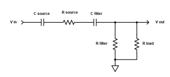
No buffering for the high pass filter means you have to include the effects of R source as well as R load.
If the source has a coupling capacitor, that should be included as well.
f = 1 / ( 2 x Pi x Reff x Ceff )
Where R effective = R source + ( R filter // R load )
and C effective = C filter x C source / ( C filter + C source )
If the source has a coupling capacitor, that should be included as well.
f = 1 / ( 2 x Pi x Reff x Ceff )
Where R effective = R source + ( R filter // R load )
and C effective = C filter x C source / ( C filter + C source )
Attachments
Last edited:
This would go between preamp and power amp. First-order is chosen intentionally due to design requirements. I know about incorporating Rload, but not Rsource and Cload. Is Rsource the output impedance? How do I factor in Cload?
R source is the spec source output impedance.
C load is not likely to be significant unless f is high, and will complicate the calculation.
If R source is small, C load would in effect be in parallel with C filter.
So try to make C filter at least x20 larger than C load.
What cutoff frequency is this for?
C load is not likely to be significant unless f is high, and will complicate the calculation.
If R source is small, C load would in effect be in parallel with C filter.
So try to make C filter at least x20 larger than C load.
What cutoff frequency is this for?
Last edited:
Does your source have an output coupling capacitor? Most commercial sources do.
It's likely C load will be very small and can be neglected, in a 100Hz filter.
Also need the R source and R load.
Since there are two variables and one equation, you have to choose one.
Try choosing R filter as R load /10, and see how C filter comes out.
A value for C filter around 0.1uF would be good, but may have to be larger due to R load value.
Last edited:
R load is 110k. R source is 1k
Do I consider the capacitance for the filter containing R filter + R load? Do I add R source as well?
Do I consider the capacitance for the filter containing R filter + R load? Do I add R source as well?
So a 10KΩ filter is a good load/source choice. For Xc=10KΩ@100Hz, C=0.16uF (R=~ 9K=10K//100K). For 11K (10k+1k) @100Hz, C=0.145uF. But you will not notice the difference if you just use standard cap like 0.15uF.R load is 110k. R source is 1k
Do I consider the capacitance for the filter containing R filter + R load? Do I add R source as well?
Last edited:
- Home
- Design & Build
- Parts
- Is a "production ready" RC filter literally just two parts?