Working on a smps.
A pair of N channel mosfets are testing as P type?
Using Fluke 115. Red probe in red socket. Black probe in black/common socket. Meter set to diode mode.
Removed a pair of mosfets marked 1L02AB FDP
26N40 from the circuit.
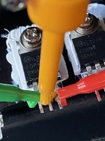
The pair of Mosfets are still screwed to the single heatsink. Mosfet printing facing me.
I did the test where I short the left and center pins. I put black probe on right pin and red probe on center pin. I get OL. While keeping black probe on right pin, I put red probe on left pin and get OL. After a few seconds I move red probe from left pin back to center pin and still get OL.
Now, even after I short the left and center pins, if I switch the probes put the red probe on the right pin and black probe on center pin, I get .49v. The center pin never measures OL even after shorting the left and center pins when measured like this.
This happens with both mostets. But there is no short from the left pin to the center pin (gate to drain).
What's the deal?
A pair of N channel mosfets are testing as P type?
Using Fluke 115. Red probe in red socket. Black probe in black/common socket. Meter set to diode mode.
Removed a pair of mosfets marked 1L02AB FDP
26N40 from the circuit.
The pair of Mosfets are still screwed to the single heatsink. Mosfet printing facing me.
I did the test where I short the left and center pins. I put black probe on right pin and red probe on center pin. I get OL. While keeping black probe on right pin, I put red probe on left pin and get OL. After a few seconds I move red probe from left pin back to center pin and still get OL.
Now, even after I short the left and center pins, if I switch the probes put the red probe on the right pin and black probe on center pin, I get .49v. The center pin never measures OL even after shorting the left and center pins when measured like this.
This happens with both mostets. But there is no short from the left pin to the center pin (gate to drain).
What's the deal?
I googled 26N40 and found this...
https://datasheetspdf.com/PDF/637343/FairchildSemiconductor/FDP26N40/1
Would ithis one have a different pin out that mine? As stated before, mine is ..."
1L02AB FDP 26N40".
With pin's wording facing me (the pair of mosfets are still screwed down to their heatsink, but entire assembly removed from circuit), gate left pin, drain center pin, source right pin.
That pin out is how I measured it. Negative probe to right/source, positive pin to center/drain. That's how I did NOT get a voltage reading. I had to put positive probe on right/source and negative center/drain to get a voltage reading. I tried shorting left/gate and center/drain to discharge, but every time I touch positive to right/source and center/drain, I always show the voltage.
Many multimeters when measuring resistance have the black probe with a positive voltage to the red probe.
Jan
Jan
These look like Chinese products. Perhaps they have a different pinout.
https://www.google.com/search?q=1L0...=gToEZdDbEYyG9u8P48qbkAE#imgrc=74eKVXcnpne1gM
Hugo
https://www.google.com/search?q=1L0...=gToEZdDbEYyG9u8P48qbkAE#imgrc=74eKVXcnpne1gM
Hugo
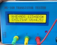
I don't know why I didn't think of using my parts tester instead of my DMM (duh!), but here are pics. The pinout is as same in the data sheet for the the other brand of 26N40. Tester says it an N enhance mosfet.What is the pinout of that device? If you don't know that, all bets are off.
Jan
But why, when I use my DMM, do I get no reading with negative dmm probe on source and positive probe on drain even after I "charge" the gate with the positive probe? I only get the .5v reading with positive probe on source and negative on drain. And no matter what I do, I can't seem to discharge the fet?
Attachments
Sounds like a leaky gate, caused probably by static damage. Once the gate oxide is damaged the device can deteriorate or fail completely. Its absolutely essential to observe anti-static precautions with discrete MOSFETs, many have no built-in protection so just touching it can destroy it.The center pin never measures OL even after shorting the left and center pins when measured like this.
Big power MOSFETs have larger source-drain leakage than small MOSFETs when off - check the datasheet for what's expected - if the leakage is larger, its definitely been zapped, but the expected leakage can be surprizingly high (not like a CMOS gate), so it may be just fine - check the numbers...
You should be able to see cutoff as that requires 0V between gate and source, and the source-drain is resistive so any test voltage will work for resistance sensing
So.
I place + to gate while touching - to drain. Release both.
Place + to source and touch - to drain. I get .33v reading.
If I leave + on source and briefly touch - to gate, then place - back to drain, I see .5v reading.
I place + to gate while touching - to drain. Release both.
Place + to source and touch - to drain. I get .33v reading.
If I leave + on source and briefly touch - to gate, then place - back to drain, I see .5v reading.
Last edited:
I'd add you will need to short the gate to source for the R check from S/D. The device tester is saying it is enhancement mode, so with 0V G/S, S/D should be moderately high resistance. Spec sheet should give the range. And as Mark says, great care with MOS devices. This is a power device, so a little more robust, but still, keep leads shorted if possible and wear a grounded static wristband when handling. And anti-static mats of course. For a device that can handle hundreds of volts and substantial current, they are surprisingly fragile.

- Home
- Amplifiers
- Solid State
- MOSFET mystery