Hey guys, is there any direct replacement TO220 replacement transistor pair that can substitute the parallel arrangement of TO92 that was manufactured with this prone to failure powersupply? The originals are C9013 but I’m tired of the reworking of these supplies when they fail, I used a 12v positive regulator I series with the B+ in to prevent alternator swinging, those hold out but is there just a drop in robust component that doesn’t need 4pcs to power it and can be durable without the inline regulator?


The D44vh10 is a fast transistor. The pin configuration is different (changed from reversed).
I had the same problem with coustic crossovers. In those, I converted to FETs and made a clamp to heatsink them to the bottom cover. It took more time but they never came back (not with that problem).
I had the same problem with coustic crossovers. In those, I converted to FETs and made a clamp to heatsink them to the bottom cover. It took more time but they never came back (not with that problem).
Last edited:
Is there a breakdown of your schematic for that FET conversion Sir Babin?
The re-repairing is eating away the pads, very frustrating.
The re-repairing is eating away the pads, very frustrating.
I looked for notes and couldn't find them. You can remove the parts that are in it and use the same basic circuit that is used for a 494 driving IRFZ44 FETs,
Use a 1k pulldown that connects between pin 7 and pins 9/10 (one resistor per pin). And use a 100 ohm for the gate resistor. You may have to lower the gate resistor value since it's likely operating ad a much higher frequency than a standard amp.
Use a 1k pulldown that connects between pin 7 and pins 9/10 (one resistor per pin). And use a 100 ohm for the gate resistor. You may have to lower the gate resistor value since it's likely operating ad a much higher frequency than a standard amp.
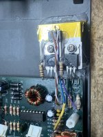
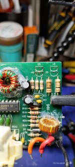
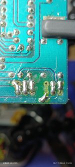
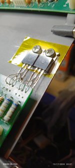
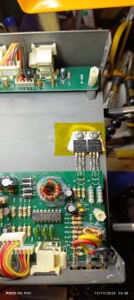
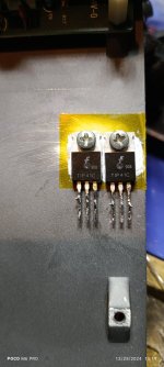
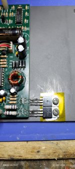
I've tried a handful of transistor replacements some held up and some didn't (first pic). I'll see if I find the list I tried.
My go to circuit now is similar to the earthquake attached; I use a MIC4424 and any PS FET I have at hands reach during the repair, I just tweak the gate resistor to suit. I use Ray Chem's "Heatpath" and some E6000 to secure the FETs and perf board to the frame.
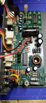
The second pic was trial, now I solder it on perf board and to the main PCB, as you mentioned, the pads and traces go pretty fast..
Prolly later on I may make a printed PCB, based on freq.
https://www.ebay.com/itm/2737999096...40QiVbuDhfiIgnWDyhG5f/GQ==|tkp:Bk9SR4rp9-zFYg
My go to circuit now is similar to the earthquake attached; I use a MIC4424 and any PS FET I have at hands reach during the repair, I just tweak the gate resistor to suit. I use Ray Chem's "Heatpath" and some E6000 to secure the FETs and perf board to the frame.
The second pic was trial, now I solder it on perf board and to the main PCB, as you mentioned, the pads and traces go pretty fast..
Prolly later on I may make a printed PCB, based on freq.
https://www.ebay.com/itm/2737999096...40QiVbuDhfiIgnWDyhG5f/GQ==|tkp:Bk9SR4rp9-zFYg
Attachments

Thanks for keeping me updated, could I use the perforated circuit board and solder pad the tabs of the FETs for dissipating, this setup does the FETs emit a lot of heat could I use that method and it runs reliable?
Minimal to zero heat from the FETs, I use the heat path and e6000 so I won’t have to drill the case.
I think most units the current draw is around 0.35A for a fully assembled.
I think most units the current draw is around 0.35A for a fully assembled.
Have you tried it without the driver, only using resistors? If you find the right combination of parts, it will greatly simplify things.
Learning from you guys I used a pair of TIP41 transistors. But without a load the the driver signal looked weird, forgot to take a photo of that, and the frequency was all over the place.
Attachments
-
 IMG_20241216_175606.jpg301.1 KB · Views: 50
 -
 IMG_20241216_175516.jpg250.9 KB · Views: 54
 -
 IMG_20241217_190003.jpg440.7 KB · Views: 50
 -
 IMG_20241217_192522.jpg297.8 KB · Views: 47
 -
 IMG_20241217_193913.jpg304.4 KB · Views: 52
 -
 IMG_20241217_193926.jpg275.8 KB · Views: 47
 -
 IMG_20241217_204654.jpg312.9 KB · Views: 59
 -
 IMG_20241217_204711.jpg214.4 KB · Views: 54
 -
 IMG_20241217_204808.jpg316.2 KB · Views: 57
 -
 IMG-20241218-WA0015.jpeg286.3 KB · Views: 44
 -
 IMG_20241225_151940.jpg279.3 KB · Views: 54
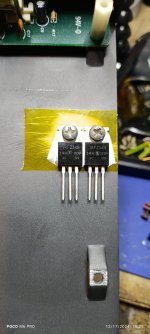
I was using a pair of 34Ns but they were getting hot, and also other techs said the FETS will eventually fail because of heat.
The TIP41 is a robust BJT and it also uses the same value resistors that was already in circuit.
But why do you say it's not a good choice?
The TIP41 is a robust BJT and it also uses the same value resistors that was already in circuit.
But why do you say it's not a good choice?
Why do (virtually) 100% of the manufacturers of car amplifiers use FETs over BJTs? They're easier to drive. They have less loss (run cooler).
If the FETs were running hot, you probably didn't add the pulldown resistors. The 1k used in one of these mods will be fine for a Z34. I've used down to 330 ohms on that driver IC and had no problems. The lower value may be needed if they're running a really high frequency.
The gate resistors should be 100 ohms or less for that FET. The same goes for high frequencies here. At higher frequencies, you lay need to go to a lower value gate resistor. Maybe 47 ohms with the Z34.
With those mods, the FETs should run very cool.
The TIP41 is a slow BJT rated for 6 amps of current. The Z34 (which isn't very robust at all, but fine here) is rated at 30 amps. The D44s that were recommended are BJTs but fast BJTs.

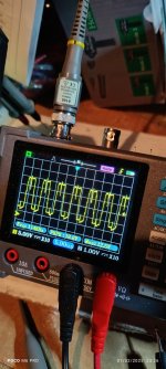
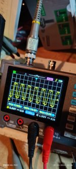
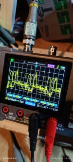
I didn't realize you are Thee Perry Babin! A follow tech told me about your guides. This is the issue i had with the FETs, with a 100 ohms resistor on the gate drives and 2 1K resistors soldered from pins 9 and 10 of the TL594 to it's pin 7. The gate drive voltage dropped down to like .5 volts. I didn't think it was enough to drive the FETs. And since the TIP 41 is a BJT i thought it would be just a drop in. Because it's actually working with the TIP 41s right now.
Were you using a multimeter or a scope for the drive voltage reading?
DCV on pins 1, 2, 15 and 16 on the 594 in your crossover?
DCV on pins 1, 2, 15 and 16 on the 594 in your crossover?
I was using a DMM and scope, not a fancy one, it's the DSO3D12. I can't really justify spending $300 on a scope nor do i have the budget.
Yes i believe so.
Yes i believe so.
I wanted the voltages on those pins.
Are you saying that with a scope, the amplitude of the drive signal dropped to 0.5v? I'd like to see a photo of that if you ever try the FETs again.
Are you saying that with a scope, the amplitude of the drive signal dropped to 0.5v? I'd like to see a photo of that if you ever try the FETs again.
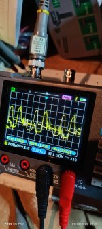
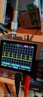
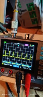
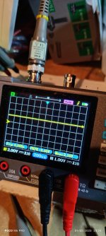
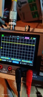
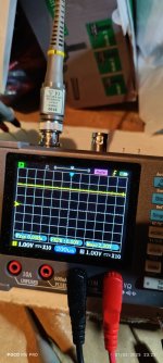
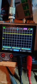
Okay, here goes... The photos corresponds with the pin number list.
Pin 1
Pin 2
Pin 15
Pin 16
Pin 9
Pin 10
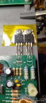
Base of TIP 41 #1
Base of TIP 41 #2
Collector TIP 41 #1
Collector TIP 41 #2
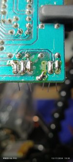
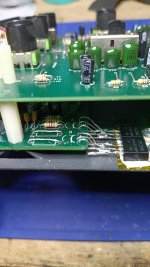
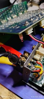
The other photos are of the circuit itself and what I've done.
Pin 1
Pin 2
Pin 15
Pin 16
Pin 9
Pin 10
Base of TIP 41 #1
Base of TIP 41 #2
Collector TIP 41 #1
Collector TIP 41 #2
The other photos are of the circuit itself and what I've done.
Attachments
-
 IMG_20250102_232639.jpg358.6 KB · Views: 42
 -
 IMG_20250102_232629.jpg358.5 KB · Views: 50
 -
 IMG_20250102_232611.jpg302.8 KB · Views: 39
 -
 IMG_20250102_232605.jpg262.1 KB · Views: 42
 -
 IMG_20250102_232548.jpg288.3 KB · Views: 38
 -
 IMG_20250102_232540.jpg286.2 KB · Views: 40
 -
 IMG_20250102_232519.jpg282.9 KB · Views: 38
 -
 IMG_20250102_232510.jpg266.9 KB · Views: 53
 -
 IMG_20250102_232450.jpg268.3 KB · Views: 44
 -
 IMG_20250102_232436.jpg280.4 KB · Views: 46
 -
 IMG_20250102_232355.jpg255 KB · Views: 43
 -
 IMG_20250102_232342.jpg292 KB · Views: 43
 -
 IMG_20250102_232647.jpg246.2 KB · Views: 36
The drive amplitude didn't drop, the pulse width was reduced due to regulation and the meter couldn't tell what happened. The scope shows plenty of amplitude to drive an FET.
The pulse width was reduced because output (rail) voltage was being fed back to the two terminals with 2.2v on them. They told the 594 that the target rail voltage had been met so the supply reduced the pulse width.
Using a multimeter to determine drive conditions is dodgy at best, regulated supplies make getting usable information even more difficult.
R9 and 13 are far too high for an FET and likely too high for the TIP41s.
I see, the meter couldn't tell waht happened?
Okay.
So it's a good thing i'm using a scope then?
Okay, so i should use lower resistances, how low? And what about R1 and R2 those are fine even if i use FETs? And if i use FETs, should i add the 2 1K pull down resistors on pin 9 and 10 of the 594?
Sorry about the questions, i just can't believe i'm talking to you.
- Home
- General Interest
- Car Audio
- Clarion MCD360 powersupply mod?