Hello all,
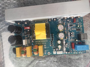
I am experimentating with an old Bass guitar amplifier (Trace Elliot GP12 SMX). The power board is defective and i will try to replace it with a new aliexpress digital SMPS one (class D) : j115d-amp 1000W
Preamp section and power amp are separated
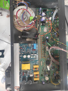
I kept the original toroidal transformer for preamp supply voltages only (19v-0v-19v) since the new board has his own SMPS supply (connected to L&N 240v)
Do you guys think it's ok like that and that there will be no stability issue with interconnected preamp and power ground and each section having his own supply ?
The new digital board supply voltages for a preamp 15v, 0v, 15v but rated at only 0,5A which i think is too low for this particular preamp (this have a 12ax7 tube that draw 0,3 amp for heaters and a lot of light bulbs and other components)
I think i will use this supply for an additional fan.
Also i wonder about safety
The chassis is a metal case with protective earth
Preamp ground and speaker are insulated from chassis. The old power board provided an audio ground to chassis connection with a 10k resistor and a 100nf cap.
The new board provided a 0v to chassis connection too but only with a blue ceramic cap, no resistor.
Is it safe like that with a floating ground for a guirar bass amplifier or should i add a resistor and if so do you think 10k like the original board will be an ok value ? Instrument and musician body are linked with the amp ground
Also the SMPS supply of the new board has two Y cap connected to chassis and i worry these could add a potential to the chassis especially in places with no PE which can happen that could create annoying and even dangerous zap?
What do you guys think ?
Thank you for your help !
I am experimentating with an old Bass guitar amplifier (Trace Elliot GP12 SMX). The power board is defective and i will try to replace it with a new aliexpress digital SMPS one (class D) : j115d-amp 1000W
Preamp section and power amp are separated
I kept the original toroidal transformer for preamp supply voltages only (19v-0v-19v) since the new board has his own SMPS supply (connected to L&N 240v)
Do you guys think it's ok like that and that there will be no stability issue with interconnected preamp and power ground and each section having his own supply ?
The new digital board supply voltages for a preamp 15v, 0v, 15v but rated at only 0,5A which i think is too low for this particular preamp (this have a 12ax7 tube that draw 0,3 amp for heaters and a lot of light bulbs and other components)
I think i will use this supply for an additional fan.
Also i wonder about safety
The chassis is a metal case with protective earth
Preamp ground and speaker are insulated from chassis. The old power board provided an audio ground to chassis connection with a 10k resistor and a 100nf cap.
The new board provided a 0v to chassis connection too but only with a blue ceramic cap, no resistor.
Is it safe like that with a floating ground for a guirar bass amplifier or should i add a resistor and if so do you think 10k like the original board will be an ok value ? Instrument and musician body are linked with the amp ground
Also the SMPS supply of the new board has two Y cap connected to chassis and i worry these could add a potential to the chassis especially in places with no PE which can happen that could create annoying and even dangerous zap?
What do you guys think ?
Thank you for your help !
Last edited:

Nobody?
I matter the most about the safety part
Do you think a 10ohm resistor between 0v and chassis ground (across the existing blue ceramic cap) or even a direct connexion is mandatory ?
Thank you
I matter the most about the safety part
Do you think a 10ohm resistor between 0v and chassis ground (across the existing blue ceramic cap) or even a direct connexion is mandatory ?
Thank you
I'm sorry I can't help you with your post but I was wondering if you ever figured it out and got it working? I've been looking to try that exact module you bought but can't find any info online about it. Do you like it?
You mention 2 different grounding systems.
Practical on-bench testing rules, but "in principle" I would:
* join preamp and power amp grounds together, with a "galvanic connection", meaning a piece of good old copper wire.
I would call that a "functional" ground, needed for preamp and power to work together.
* then I would connect one of those ground points (preferably at the preamp end) to metal chassis, for shielding, which is a different function.
* Fancy "grounding but not really grounding" schemes were invented for recording Studio or complex Stadium level Pa setups to avoid ground loops, a distinct possibility in complex setups.
For Home or small Club use?
I would just ground everything through real copper wire and call it a day.
When/if you have a real ground loop problem, then start solving it.
Reaching protective ground through a resistor, capacitor or couple diodes gives me the chills, serious.
Call me an old school dinosaur but in case of trouble it should freely pass as many Amperes as needed to trigger Mains circuit breakers, think 10-20A or more.
jm2c