Hey guys, I wondered if anyone could give me any tips or insights of what've done so far. I need to know the following:
1- Is there anything wrong with my circuit?
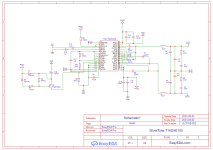
2- How to connect XL60? Pin 3 and 6 together? Only pin 3? Or only pin 6?
([Warn] : Found some components Pins floating, suggest placing No Connect Flag on the Pins : U2.2,U2.6,U3.2,U3.6)
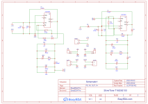
3- Wanted as well to know, recommended Power Rating for the Resistors
4- PCB Design: Anything I should have done in a different manner?
Thanks in advance

1- Is there anything wrong with my circuit?
2- How to connect XL60? Pin 3 and 6 together? Only pin 3? Or only pin 6?
([Warn] : Found some components Pins floating, suggest placing No Connect Flag on the Pins : U2.2,U2.6,U3.2,U3.6)
3- Wanted as well to know, recommended Power Rating for the Resistors
4- PCB Design: Anything I should have done in a different manner?
Thanks in advance
Attachments
Anything I should have done in a different manner?
- You should ask moderators to move the thread to class d forum
- You should explain your circuit. E.g. what are you using the two xl6019s for?
- your pcb still has no traces, so you can't expect useful comments
- you need to study datasheets for correct connections
- for correct resistor power rating maybe simulate the circuit with your planned specifications
- you may consider buying a complete (cheap!) tpa-amp module instead of re-inventing the wheel. or look up a project in the class-d-forum.
- also keep in mind that there are better successors to the tpa3116 ...
For the fast switching currents inside these amps you need to learn more modern ways of low inductive pcb layout. And blocking caps like C14 that size are an absolute no-go for instance. When I started designing my TPA3116 amps, I first studied the data sheet and specially layout considerations and EVM layout.
"You should ask moderators to move the thread to class d forum"
If any moderator would be so kind to do so I would apreciate it
"What are you using the two xl6019s for?"
They're for stabilizing and boosting Voltage
"your PCB still has no traces, so you can't expect useful comments"
I did not make any traces yet, because I was hoping if anyone could tell me if they're are on the right place, but I suppose you're right
"you need to study datasheets for correct connections"
You're absolutely right
"For correct resistor power rating maybe simulate the circuit with your planned specifications"
OK
"You may consider buying a complete (cheap!) tpa-amp module instead of re-inventing the wheel. or look up a project in the class-d-forum."
this is something I really want to do
"Keep in mind that there are better successors to the tpa3116"
yeah... I know... Specially the 325*... But I want this one
" And blocking caps like C14 that size are an absolute no-go for instance"
Because of anything related to thermal? Or just because of space? It's a Polypropylene Film Capacitor. Should I design it with other types of materials? I want to avoid TH components at all costs
Film caps are an absolute no-go as blocking caps. Have a look at the evaluation module from TI. With that beginner level of knowledge you are you are at the beginning of a steep learning curve.

"Film caps are an absolute no-go as blocking caps"
Would you be so kind and explain why? I'm all ears
Would you be so kind and explain why? I'm all ears
So what then? Ceramic C0G or X7R?
But you mean all of the capacitors, should be Ceramic? Apart from the electrolyte ones
But you mean all of the capacitors, should be Ceramic? Apart from the electrolyte ones
No expert but 1 uF in 2.5 mm film caps perform very good as coupling caps. Small. Superior. Too bad but only one brand produces these.
Decoupling caps etc should be SMD X7R as minimum standard. The higher the voltage rating the better.
Decoupling caps etc should be SMD X7R as minimum standard. The higher the voltage rating the better.
Ok but these are so small that you can bend the pins and use them as SMD 😀 Wima MKS2 in 2.5 mm pitch are wonderful caps. You will not regret using film caps at the inputs. PPS film caps exist in SMD ....
BTW for someone that wants to avoid TH parts at all costs you have a lot of TH caps in your design!
BTW for someone that wants to avoid TH parts at all costs you have a lot of TH caps in your design!
OK so you want to avoid SMD caps. Impossible with class D when it is about decoupling supply pins. Input caps can be small TH film caps just like output filtering caps. Small sized and short lead wires.
Last edited:
- Home
- Amplifiers
- Chip Amps
- Building the TPA3116