Has the Elektor forum disappeared ?
Well it is not audio related , unless you count the clicker .
Has anyone made this radiation detector with a photo diode BPW 34 ? (Elektor june 2011, and the improved one november 2011).
A while back I bought 2 different BPW34 , Osram and Vishay and the BC849C.
But November 2011 is the improved version with JFET + opamp.
I thought to try the transistor version first , but it has to be shielded and the BPW covered, so why bother , better to go for the better version.
Not sure why Elektor didn't directly go for a JFET opamp or even a CMOS one without the now harder to find JFET BF245 or other.
I know too little of analog circuits to adapt the JFET version to a straight opamp one .
I have 2 good opamps for this: OPA196 in super small Sot23-5 and OPA197 in soic 8.
Don't know how much I can post here , with copy rights and stuff , but it is from 2011 , 12 years ago.
Attachments
Use a LMC-something instead of the 358, and connect directly the photodiode+ 20M resistor (or more) to the + input of the opamp and scrap the FET and its loading resistor.
The foot of the 20M could be returned to a voltage of 1 to 2V instead of GND, to increase the dynamic range
The foot of the 20M could be returned to a voltage of 1 to 2V instead of GND, to increase the dynamic range
Thanks Elvee .
Can it be as simple as this ? Then why did Elektor go to the trouble of adding a JFET.
Not sure what you mean with : " The foot of the 20M could be returned to a voltage of 1 to 2V instead of GND, to increase the dynamic range"
Elektor writes that a higher voltage over BPW34 is better because it reduces the capitance . The text says gives a overall voltage gain of 30.000 , but I only see about 33 x 33 = about 1000 gain. How am I wrong ?
Attachments
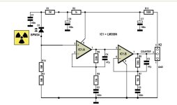
It increases the input impedance and lifts the DC voltage by 1 or 2V.Can it be as simple as this ? Then why did Elektor go to the trouble of adding a JFET.
With an opamp like the 358, this is necessary because it requires a bias current of several tens of nA. With a LMCxyz or a TLCzyx, the input current is fA, perfectly OK, but the input will be very close to the GND.
To give it a little more leg room, you can tie the 20M resistor to a divider made of 1K5 and 10K for example.
As it is, the gain of the circuit is 1000 indeed
Theoretical value is 2200, but in practice it will be somewhat lowerCan you tell how much gain the transistor/transistor amplifier has ?
Of course . Like I said : OPA 196 or 197.Yes, but with something else than a 358
Thanks Elvee .
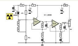
Still a bit bothered by the 30.000 gain for the JFET version in the Elektor text , now that the tr/tr version is also more than 1000.
Does the JFET step have gain or is it just a 1:1 buffer ? Sorry , I can't tell , I'm not that familiar with JFETs.
Also is R2/C6 necessary ? With the 10k/1,5k , it is a 800 mV drop over R2 . OR replace them with higher value : 100k/15k ?
Since the BPW34 is not AC coupled , can current fluctuations over R11 cause false signals on the output ?
The jFET has a gain of 0.9, or thereabout.
R2/C6 is certainly necessary with the FET; much less so with the direct connection to the photodiode, but it remains necessary with the foot divider.
100K/15K is certainly OK, going much larger would risk noise collection from both ends of the 20M.
The RC cells with R2 and R11 have a large enough time constant to rule out the possibility of false signals
- Home
- General Interest
- Everything Else
- Radiation detector with photodiode BPW34 from Elektor 2011