
Hi Daniel,
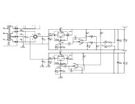
the answer is quite simple: In the active situation there is a positive voltage between LM317 input and output. When you switch off the mains switch, the voltage on the output side of the regulator MAY fall slower (e.g. due to large capacitance and small current at the output) than on the input side of the regulator. This would cause a negative voltage between LM317 input and output which could/would destroy the regulator. The diode from LM317 output to input will limit the reverse voltage to ~0.7V and also "dissipate" any reverse current, this way protecting the regulator from failing. the max. reverse Voltage the regulator can tolerate is given in the Datasheet.
Greetings,
Winfried
+1 for diodes. You'll actually want four of them: One from VOUT to GND on both halves. And one across the regulator (input to output) on both halves. They should be reverse biased under normal operation. They protect the regulator if the output voltage ever exceeds the input voltage and against reverse polarity on the output. These conditions may occur during startup and shutdown and often lead to intermittent failures of the regulators. A few cent spent now will be worth real money down the road in repairs.
That aside, your circuit should work just fine.
Tom
That aside, your circuit should work just fine.
Tom
Thanks, I will insert them on pcb.
one more question, the connected gnd is ok to attach to dac gnd? The two 7815 is to power opa at dac output.
BR //Daniel
one more question, the connected gnd is ok to attach to dac gnd? The two 7815 is to power opa at dac output.
BR //Daniel
Hi Daniel,
If your circuit is designed for symmetric +/- 15V supply, the ADC circuit Ground and the supply ground must be connected.
So, your application is an analog DAC Output buffer?
Which OPA do you use for that?
Would you share the schematic and its connection to the original DAC output?
Did you consider so use the DAC power supply for the buffer? That may be an option!
Greetings,
Winfried
- Home
- Amplifiers
- Power Supplies
- Dual 15v supply