Morning y'all.
Have aforementioned machine. Bought it because a previous owner had tried to replace dac chip with a piggyback 2x TDA1541A double crown - paid less than what you would pay for a single double crown. I was chip harvesting but now want to get this unit working because it is so nice. I'd read that they were heavy, but hadn't grasped what that meant in reality - yep, it's heavy!!
There has been a bunch of work done on this be previous so I have contend with all of that in order to find faults. I cannot easily return it to original baseline as a start point. It has been put in NOS, the SAA chip has been removed and was not supplied. As manufactured this unit used the non-A TDA1541 chip but it came to me after attempt to use 1541A chips. I don't have and non-A chips myself so will continue with the bodge. I have to check to see if additional timing cap was added for oscillator.
My first question is relatively simple
I'm pretty sure that the CDM1 should spin up when the cd door shuts regardless of there being a disc present or not?
Currently it does NOT spin up when no disc present - but it does when you insert a disc. It does not read TOC
I've mucked about with these Philips and Marantz TDA1541 players a bit so I'm not a complete novice but I'm also far from being expert repair tech.
The first thing I did was to replace the usual suspect 33u axial cap on the laser control board - this has been my simple remedy in the past - but alas this machine requires something more. Today I will go through and reflow solder, griplets etc. and follow any other suggests I can find online.
The platter motor will spin up only after the laser have found focus. Without a CD inserted the swing arm goes to the innermost position, the laser emits light and searches focus by moving 3 times up-down. If no focus found, the platter does not spin.

The microprocessor requires a reflection from the laser to spin up.
If it spins up, is it spinning fast enough?
If it is, replace the laser and that will show you which direction to go.
If it spins up, is it spinning fast enough?
If it is, replace the laser and that will show you which direction to go.
The CDM1 drive is virtually indestructible...if nobody messes with power for the laser diode, that is.
Known problems AFAIK:
Known problems AFAIK:
- capacitors
- bad solder joints
- solder flux residues, or something in that sense, causing "bridges"
- spindle eating its way into thrust bearing therefore altering focus distance
- spindle bearing longing for oil.
Check also the capacitors on the main board, 2215 (2µ2) abd 2217 (1µ5) their angled legs
might short to the copper ground plane of the board. https://www.diyaudio.com/community/...wing-arm-alignment.259559/page-3#post-5123495
might short to the copper ground plane of the board. https://www.diyaudio.com/community/...wing-arm-alignment.259559/page-3#post-5123495
1)
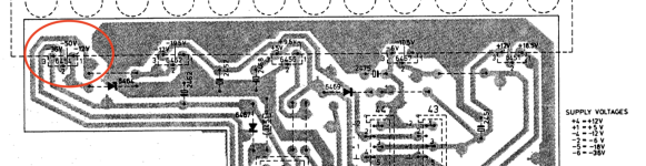
So I have the CD304 mk2 service manual
Where it gives the legend for the voltages to expect at the connectors of each PCB these values don't appear to make sense - or at least not with what I am measuring
Where the manual indicates a +/-1 value I generally get voltages more like what the legend says is +/-4 value.
This is consistent across the PCBs where I take measurements that should measure +/-5v according to the legend they measure closer to +/-12v
Can anyone shed light on whether this is a a known error in this manual?
2)
On the regulator circled in red. For the pin that says it should measure -12v I am getting double that -24v. I have tested with a new regulator and got the same.
These two things 1&2 could be related ???
Attachments
- Home
- Source & Line
- Digital Source
- Philips CD304 Mk2 repair