Before I make prototypes, which resistive vent you expect to be best.
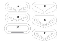
Speaker will be used close to the wall. Fullrange driver crossed to the woofer at 350Hz.
CNC machined, stacked plywood construction.
All prototypes will use Acoustic Thinsulate 7.7 kg/m3 inside.
Prototype C will be using wool felt sheet , 20 mm, 230 kg/m3 covering round holes from the inside.
The rest will use wool felt sheet 2 mm thick, 230 kg/m3 covering the vent hole.
Attachments

Last edited:
The vent is for the bass?
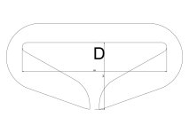
Forget the first 2, i doubt they are “flexible” enuff. But as pictured in the left image in the 3rd pdf is where i would start.
Start with a few holes and stop when it goes right.
This cross-section shows probably the most advanced aperiodic box so far, but the woofer is speciifcally designed. It is the whole box not the vent. That is a crude, but often effective method.

What is the predicated response with the woofer you plan in the (too small) box of what volume?
dave
Forget the first 2, i doubt they are “flexible” enuff. But as pictured in the left image in the 3rd pdf is where i would start.
Start with a few holes and stop when it goes right.
This cross-section shows probably the most advanced aperiodic box so far, but the woofer is speciifcally designed. It is the whole box not the vent. That is a crude, but often effective method.
What is the predicated response with the woofer you plan in the (too small) box of what volume?
dave
Dave,
The vent is for fullrange flat cone bending wave driver, crossed at 350Hz to the woofer.
You would start with C , because it can be tuned with holes and density of absorption?
Can others be tuned pulling absorption material trough taper, so that it gets denser at the end of the taper?
Is taper too short to be aperiodic TL?
The vent is for fullrange flat cone bending wave driver, crossed at 350Hz to the woofer.
DML?
Then i would recommend a short highly tapered apeiodic TL. If it is sealed at leasta half-wave length long, if open quarter-wavelength, based on at least an octace below the cute-off, longer does not hurt. Then damp such thatthe density is very low near the driver and becomes denser as you approach the terminus.
This shows the midTL in Tysen V2, and the impedance of the similar line in Tysen V1.
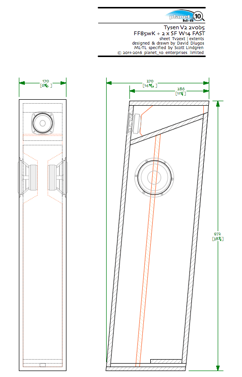
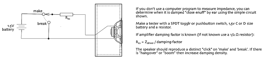
You can tune the damping using an impedance measurer — you want to work towards flat impedance response, or use GM’s click-test.
dave
Yes, dml.
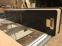
Allright, tapered, but dimensions are set, triangle version of enclosure is 18cm deep, rectangle 14cm deep. I will have to choose the best I can make. Will use impedance measurer.
I have tried 12cm deep leaky enclosure for dml, had to cross at 400 hz with 4th order high pass, could not tame resonances using it lower.
Attachments
Last edited:


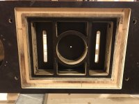
Potential midTweeter enclosures? What are the different sections all about?
The volume is more than sufficient for the midTL.
dave
The volume is more than sufficient for the midTL.
dave
- Home
- Loudspeakers
- Multi-Way
- Aperiodic vent for shallow, close to the wall speakers