I'm interested in hearing how my speaker's sound changes when the room reflections are more controlled. I see lots of thin single material panels however I think I would prefer a wide band multilayer absorber to uniformly reduce reflections and not disturb the spectrum profile too much.
I found a some material tables Material Tables and a multilayer calculator Acoustic Modelling that both seem reasonable. I have (arbitrarily) limited the panel depth to 20cm. I'll post the design with measurements before/after.
If you've built one, I'd like to hear your experience / impression.
Panels Built and room measured:
1) Standing panel (H183 x W61 x D20 cm) - Standing Panel
2) Helmholtz panel (H183 x W61 x D20 cm) - Helmholtz Panel
3) Wall panel RockWool (H122 x W61 x D80 cm) - Wall Panel - RockWool
4) Wall panel foam pyramids ( 91H x W61 x D5 ) - Wall Panel - Foam Pyramids
Last edited:

First kick at the can, V1 panels
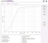
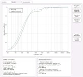
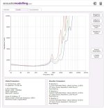
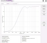
Using a multilayer panel I can get a smooth response down to approx 110Hz, 50% absorption (-3dB cutoff). In order to extend the attenuation a little lower I would need a separate Helmholtz panel, but these are usually high Q, narrow BW and might be more usefull to reduce specific room modes.
Using a multilayer panel I can get a smooth response down to approx 110Hz, 50% absorption (-3dB cutoff). In order to extend the attenuation a little lower I would need a separate Helmholtz panel, but these are usually high Q, narrow BW and might be more usefull to reduce specific room modes.
Attachments
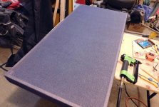
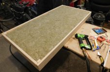
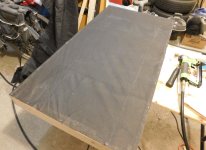
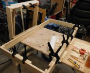
These are build pics for the first 2 panels (v2, H183 x W61 x D20 cm). Still not sure how to measure them, other than RT60, or maybe sonogram before/after. They seem to have helped deaden the room.
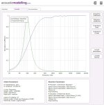
pic1 - the predicted panel absorption using the calculator
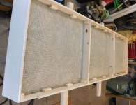
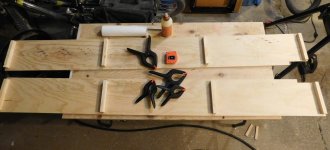
pic2 - side panels
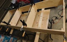
pic3 - assembly with braces
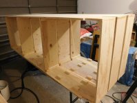
pic4 - 3 panels built, only the first 2 have this fill design
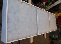
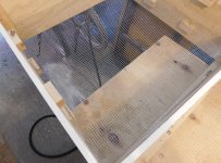
pic5 - rear screen inserted (1/4" mesh) the hold fill in place
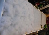
pic6 - Rockwool SafeNSound 80mm (3.5") added
pic7 - poly fill ~60mm compressed to 40mm
pic8 - poly fill side with screen to hold fill in place
pic9 - Rockwool side with holding screen and air gap 70mm
pic10 - 2 assembled panels, without grill cloth (still looking for the right one)
pic1 - the predicted panel absorption using the calculator
pic2 - side panels
pic3 - assembly with braces
pic4 - 3 panels built, only the first 2 have this fill design
pic5 - rear screen inserted (1/4" mesh) the hold fill in place
pic6 - Rockwool SafeNSound 80mm (3.5") added
pic7 - poly fill ~60mm compressed to 40mm
pic8 - poly fill side with screen to hold fill in place
pic9 - Rockwool side with holding screen and air gap 70mm
pic10 - 2 assembled panels, without grill cloth (still looking for the right one)
Attachments
-
 PIC10-DSCN1382r.jpg90.1 KB · Views: 200
 -
 PIC9-DSCN1381r.jpg171.5 KB · Views: 173
 -
 PIC8-DSCN1380r.jpg127 KB · Views: 162
 -
 PIC7-DSCN1379r.jpg78.7 KB · Views: 173
 -
 PIC6-DSCN1367r.jpg134.2 KB · Views: 170
 -
 PIC5-DSCN1365r.jpg271.3 KB · Views: 176
 -
 PIC4-DSCN1355r.jpg115.1 KB · Views: 173
 -
 PIC3-DSCN1353r.jpg119.4 KB · Views: 169
 -
 PIC2-DSCN1348r.jpg79.2 KB · Views: 186
 -
 PIC1-Panels FR V2a.jpg113.2 KB · Views: 186
Very nice.
I have only built a one inch thick wool 4' x 6' panel, but found that spacing it a few inches from the wall surface
seemed to help more than expected. This may not be relevant to a much thicker panel though.
I have only built a one inch thick wool 4' x 6' panel, but found that spacing it a few inches from the wall surface
seemed to help more than expected. This may not be relevant to a much thicker panel though.
Can you show the difference for your panel, between flush on the wall, and spaced out 20 cm from the wall?
I would expect the attenuation would extend to a bit lower in frequency for the spaced arrangement.
Have you considered large holes in the walls of the compartments, or else building this as more of an open frame
without much inside wall surface (aluminum frame, etc.), to reduce reflections? That would also reduce the weight.
Last edited:
My panels have a solid back, so its the same.
But I can increase the rear air gap by 20cm to show what would happen. This calculator model assumes that the rear panel is air tight and your application probably leaks out the side. This give the general idea.
[edit - missed a question] The panel is fairly minimal right now, but with open/fractional side panels the sound could leak out the sides, and I want to force it into a predictable path (even the return path) through as much absorber as possible.
Attachments
Last edited:
Ok, can you also model this with the back open, spaced away from the wall, by say 20 cm?
That should extend lower in frequency. Just curious.
Maybe with your outside panels solid, and the inside panels mostly open, would be a good compromise.
If anything, scatter from the back panel would travel through more material this way.
That should extend lower in frequency. Just curious.
Maybe with your outside panels solid, and the inside panels mostly open, would be a good compromise.
If anything, scatter from the back panel would travel through more material this way.
Last edited:
Yes, that looks like the rear wave interfering with the front wave, like in a dipole speaker.
I think the inner panels should be mostly open, with just enough structure to hold the contents in place.
Like chicken wire, aluminum angle stock, etc. Much lighter for hanging up, too.
I think the inner panels should be mostly open, with just enough structure to hold the contents in place.
Like chicken wire, aluminum angle stock, etc. Much lighter for hanging up, too.
You measure the absorption coefficients with doing a measurement before and after you install it in a room. And some math.
But it's hard to get reliable results at low frequencies when modes are all over the place. That's why building an echo room working at low frequencies is not easy ...
Did you search for BCA (broadband compact absorber)? There are a few pdfs online, I realised such a build in my listening and recording room and they work good at lower frequencies. I would suggest 2x 10cm of Caruso Isobond (or similar material) and 2x1m metal sheets of different strength depending on position in the room (I used thinner sheets at the ceiling and thicker ones towards the edges).
Do you have a link? There seem to be a few.
I was also going to build a Helmholtz absorber (panel#3) as soon as I figure out what freq I need to tune it to.
I was also going to build a Helmholtz absorber (panel#3) as soon as I figure out what freq I need to tune it to.
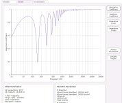
I measured how much poly I actually used and determined the density used (16.3Kg/m3). The update does not make much difference.
I also compared a single layer of RockWool to a dual layer of RockWool+Poly using the same panel dimensions. The absorption looks very close but the 2 layer panel's acoustic impedance is closer to air (413 Ry) so that should result in less reflection.
I also compared a single layer of RockWool to a dual layer of RockWool+Poly using the same panel dimensions. The absorption looks very close but the 2 layer panel's acoustic impedance is closer to air (413 Ry) so that should result in less reflection.
Attachments
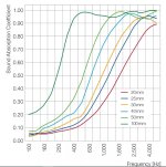
There are a few commercial absorber panels using Basotect (BASF) BASF Basotect spec . A chart for comparison, it was measured using an impedance tube according to BASF.
Attachments
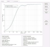
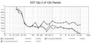
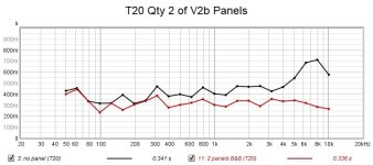
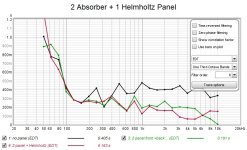
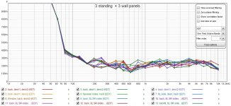
A few REW measurements of the room with and without 2 panels. It looks like I can easily measure the effect of adding them. REW has a few views of the decay time, I prefer the EDT curve. Panel location has an effect, they were just placed them standing in the center of 2 walls, with mic at the listening position. These V2b panels are effective from ~120Hz (@A=0.5).
Attachments
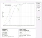
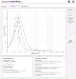
The 3rd panel was made into a Helmholtz absorber to extend the absorption curve a little lower, . It was the only design I found that could go low without being excessively deep.
PIC1 - the predicted absorption response, each chamber (3) is tuned differently to spread out the absorption range and complement the first 2 panels
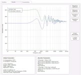
PIC2 - the acoustic impedance
PIC3 - simple punch tool made from a 1/2 copper pipe to create the holes in XPS
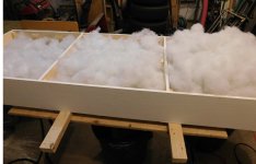
PIC4 - poly fill was weighed to get the needed density (flow resistance) and teased to fill the chamber
PIC5 - XPS sheets caulked in place
PIC6 - foam acoustic tile sheets covering the holes (this is for HF only, they are transparent to LF)
PIC1 - the predicted absorption response, each chamber (3) is tuned differently to spread out the absorption range and complement the first 2 panels
PIC2 - the acoustic impedance
PIC3 - simple punch tool made from a 1/2 copper pipe to create the holes in XPS
PIC4 - poly fill was weighed to get the needed density (flow resistance) and teased to fill the chamber
PIC5 - XPS sheets caulked in place
PIC6 - foam acoustic tile sheets covering the holes (this is for HF only, they are transparent to LF)
Attachments

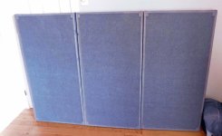
Wall panels. These are H122 x W61 x D80 cm, only because it's an efficient use of lumber sizes and RockWool. These panels are thin (80mm) and absord down to ~250Hz (A=0.5).
PIC1 - intended design using the calculator
PIC2- simple frame with some edges reinforced for hanging (vertical or horizontal)
PIC3 - back cover, fabric (coarse garden fabric) to allow air flow
PIC4 - RockWool SafeNSound 80mm thick
PIC5 - front cover, fabric looks like speaker grill cloth, except its denim blue color, and maybe too thin as the frame shows through
PIC6 - 3 panels for testing
Attachments
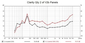
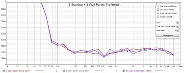
The test results measuring the room with all panels. PIC1 shows the variation from putting the panels in different positions, with no clear winner. I'm "assuming" that I want a smooth relatively even curve to make the decay time less frequency dependent.
Attachments
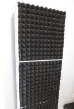
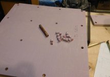
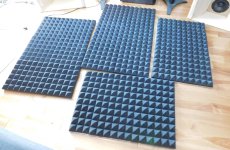
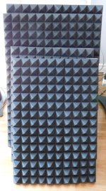
These wall panels use 2" foam pyramids (12"x12") mounted on cardboard (large) and foam board (smaller). Total of ~20ft2 coverage added.
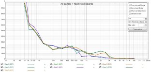
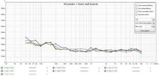
The room measurements (with all 10 panels) are around the listening area to see how sensitive the measurements are to location. The foam is really only effective >~600Hz based on the decrease in EDT.
The room measurements (with all 10 panels) are around the listening area to see how sensitive the measurements are to location. The foam is really only effective >~600Hz based on the decrease in EDT.
Attachments
- Home
- General Interest
- Room Acoustics & Mods
- Wideband Multilayer Absorber Panel