I've got a couple of QCC3008 modules that I just can't connect to via SPI (I keep getting an 'error detecting chip type' message in the WIN1.0.167 version of PSTool) and I'm wondering if its because they have the later type bluetooth module on them rather than the older BTM308-C. My USB to SPI interface is working fine on the older modules (8630), I've tried connecting SPI_En directly to 1V8 and 3V3 via a resistor. I can't even change the firmware as Blueflash doesn't recognise the chip.

This is the older type

This is the later ones I've got.
I was just wondering if anybody had had success connecting to these later type modules as in the Youtube video series from Dariee, he uses the older type and I can't find anything out about the later modules.
Many thanks.
This is the older type
This is the later ones I've got.
I was just wondering if anybody had had success connecting to these later type modules as in the Youtube video series from Dariee, he uses the older type and I can't find anything out about the later modules.
Many thanks.
Hello Horson!
I have the same problem! Have you had any progress sins may?
I run PSTool v2.6.8.1467
and ADK Configuration Tool v"Qualcomm ADK".
I have the same problem! Have you had any progress sins may?
I run PSTool v2.6.8.1467
and ADK Configuration Tool v"Qualcomm ADK".
Last edited:
Yes and no. I eventually bought some apt-x qcc3008 ones from tinysine and they worked for the most part (had to try a couple of ADKs, most versions of PSTool were fine), so I know it wasn't my setup that was wrong. I think they just stopped making them customisable, the swines.
I just had some luck! I connected 3,3V via 1k ohm to enable. On the blue card, enable was not connected, but on the black card it was requierd. I can now use both PSTool and ADK Configuration Tool 🙂
I have purchased several QCC3008 ATP-X TWS boards for a project and I cannot get any of these to connect. My first test board worked great until I overheated it removing header pins 🙁. I have the .PSR file from that, I thought maybe I can just use that to flash the replacement boards? I have tried everything I could find online, no luck. I have the pogo pin adapter and now soldered directly to the board. 🙁 My first demo board had troubles connecting but worked 100% of the time once I soldered cables to the board to connect the CSR.
The weird thing was I was able to briefly connect one time using the pogo pin adapter and I was able to dump the original .psr file. I also was able to connect and change the friendly name (bluetooth name) using one of the ADKs for two of the boards.
Do I need to do some kind of erase and reflash the boards with an alternate .psr I have from my original demo test board?
I have tried every combination below and received different errors. I'm really stuck on this and appreciate any advice! Thx
SPI_EN Pin:
- 1.8v from CSR USB-SPI
- 3v3(+resistor) 1K, 10K and 22K Ohm resistors to the enable pin does not give any other results
- ADK_CSR867x.WIN4.2
- ADK_CSR867x.WIN4.3.1.5
- ADK_QCC300x.WIN.1.0.167
- ADK_QCC300x.WIN1.0
- ADK_QCC512X_QCC302X_WIN_6.4.2.26
- Error detecting chip type (Read failed on USB-SPI)
- application was unable to find a look-up table on the chip
- SPI communications failed. Failed to stabilize reads after disabling Shallow Sleep.
- partial connection? data is listed but I cannot change any settings. "Friendly Name" does not appear in the list either. Trying to reconnect gives "Verified Read Failed" error
- AHI_ERROR_TRANSPORT_CONNECTION_TIMEOUT
Hello Hotwired89!
I understand your frustration, I sat myself for many hours...
Guess you've tried more than one of the cards?
I understand your frustration, I sat myself for many hours...
Guess you've tried more than one of the cards?
Hi Blåtand 
I have tested 3 of the 4 from the first batch I purchased, all with same results thus far. I have two more arriving in a few days from a different seller. I have been reading through another helpful diyAudio forum post here CSR8675 programming guide w. software and tons of CSR info. Trying to understand how a flash erase is done and if or how I can reflash with the .PSR file I have. (or if other files are needed??)
I did download the big 2GB CSR file package created on that other forum posting so just trying to understand where to go from here. I have 10 custom made PCBs done and the QCC3008 is the only issue. I have tried to connect with my pogo pin adapter and recently I soldered directly to the board and made a JST connector so I can plug in and test that way. There is a resistor on the protoboard between V and E pins, but I also have the orange pin which is 1v8 from the CSR USB SPI programmer.
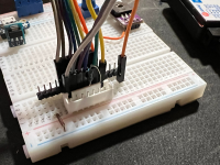
Here are some photos of my set up for testing.
Ignore those other components I was testing some other things on a different project

I had the resistor soldered to the top of the pogo adapter pins but removed this in favor of the protoboard. Continuity tested after to make sure I did not create a jump fault between pins

1K, 10K and 22K ohm resistors were tried between V and E pins
1v8 from CSR USB SPI is also on the right (orange wire) for testing
3v3 was never used for SPI_EN, I believe this will kill the board


I have tested 3 of the 4 from the first batch I purchased, all with same results thus far. I have two more arriving in a few days from a different seller. I have been reading through another helpful diyAudio forum post here CSR8675 programming guide w. software and tons of CSR info. Trying to understand how a flash erase is done and if or how I can reflash with the .PSR file I have. (or if other files are needed??)
I did download the big 2GB CSR file package created on that other forum posting so just trying to understand where to go from here. I have 10 custom made PCBs done and the QCC3008 is the only issue. I have tried to connect with my pogo pin adapter and recently I soldered directly to the board and made a JST connector so I can plug in and test that way. There is a resistor on the protoboard between V and E pins, but I also have the orange pin which is 1v8 from the CSR USB SPI programmer.
Here are some photos of my set up for testing.
Ignore those other components I was testing some other things on a different project
I had the resistor soldered to the top of the pogo adapter pins but removed this in favor of the protoboard. Continuity tested after to make sure I did not create a jump fault between pins
1K, 10K and 22K ohm resistors were tried between V and E pins
1v8 from CSR USB SPI is also on the right (orange wire) for testing
3v3 was never used for SPI_EN, I believe this will kill the board
Attachments
One mistake I made when the little processor boards went from blue to black was to miss that they lowered the supply voltage. With the blue cards I could drive 5.0V, to the black cards I drive 3.3V. I'm using cards without their own DC/DC...
The audio output on the black ones is extremely noisy when the unit is not connected to bluetooth, so I put 560ohm between L/R and G.
The audio output on the black ones is extremely noisy when the unit is not connected to bluetooth, so I put 560ohm between L/R and G.
I got almost same problem before as OP mentioned.
Thing happend by QCC module that I bought from AliExpress.
Sellers advertises that their modules are "fully programmable", but it definitely didn't.
That time I look around whole inthernet inluding google and multiple of deep chinese archives to program it.
But my computer could not even recognize my QCC module - any kind of drivers and flash tools didn't work.
Getting help from sellers and tools they provided was also totally useless.
Same environment, same configuration as internet describes... What I only got for 2 years is fatal crash of my computer and re-installation of windows.
Now I gave up for it, and looking for ESP modules to make my own bluetooth audio module.
You also should check it out. ESP series provides lots of functional and pricing advantages rather than QCC modules.
I've tried 1K between 3.3V and Enable on the chip, still cannot connect with ADK or PSTools 🙁Hi Hotwired89!
I took 3.3V from SPI to connector V, and 1k between 3.3V and Enable...
Silly question, should I also power the board separately on the VCC and GND pins in addition to connecting the SPI programmer?
Last edited:
@xeroname I'm currently stuck to the QCC3008 footprint now that I have 10 built PCBs.
I even considered building my own QCC3008 TWS boards so that I can buy the separated Bluetooth chips which I would think come "unlocked"?
Do you have any links or recommendations for these ESP series you mentioned?
Thank you
I even considered building my own QCC3008 TWS boards so that I can buy the separated Bluetooth chips which I would think come "unlocked"?
Do you have any links or recommendations for these ESP series you mentioned?
Thank you
Hello Hotwired89.
I recommend ESP32-C3 series if your goal is only bluetooth audio receiver.
You can buy it single processor or integrated module package.
Here's the module from MOUSER. It costs only $2, and the datasheet kindly describes almost everything.
https://www.mouser.kr/ProductDetail...P32-C3-MINI-1U-H4?qs=pBJMDPsKWf1ZgoQcnZrrOA==
Note that you should build your own PCB to program it.
Still though what you need is ESP module and few resistor and capacitor.
About how to program it, you can use open-source github repository shared by others :
https://github.com/pschatzmann/ESP32-A2DP
Hope this would help.
Also ESP provides web product selector to select your own by requirements : https://products.espressif.com/#/
Hi Hotwired89!
You wrote that you connected 1V8 to V from SPI, I used 3V3. But maybe I misunderstood you?
You wrote that you connected 1V8 to V from SPI, I used 3V3. But maybe I misunderstood you?
Hi xeroname, I should mention my project requirement uses Hands-Free Profile, so I have a Microphone hooked up as well here. I didn't see anything right away that mentioned ESP will work this way. I'll look into that some more. Thank you
Hi Blåtand,
I realize my earlier description might not be a clear or "proper" way to explain how I hooked it up. Sometimes a simple picture is much more understandable than trying to explain over text 🙂
Here's a picture of the different connection tests I have done. FYI, the red box side is 1V8 or 3V3 from the CSR USB-SPI device itself. You can see I used 1V8 directly to SPI_EN, OR one of the different resistors used with 3V3 from the CSR device to the SPI_EN. The QCC device was always powered up with 3V3 from CSR during tests.
Just received two new boards from a different vendor. Time to see if these connect unlike the others..
I have tried both 1V8 and (3V3 + 1K Resistor) on the enable pin. Both attempts with various versions of PSTools gives me similar results on the new boards. Some times it does like a false read with PSTools where I can see some results but they aren't all there and I cannot set any values. I cannot see the "Friendly Name" setting to change the Bluetooth display name. I am beginning to think maybe something is wrong with my CSR USB-SPI programmer? or some other settings?
usbspi.sys

I tried changing drivers to, restarting and testing again


usbspi.sys
I tried changing drivers to, restarting and testing again
Driver changes did not change anything..
I have tried CSR USB-SPI Drivers:
2.4.0.0
3.0.0.2
4.0.0.0
I have tried CSR USB-SPI Drivers:
2.4.0.0
3.0.0.2
4.0.0.0
- Home
- Source & Line
- Digital Line Level
- Can't connect to QCC3008