Inevitably during tube builds it becomes obvious that at least 10 megohms/volt DC is needed, especially on grid circuit measurements.
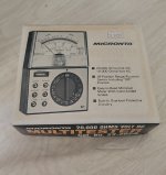
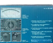
So this guy, from an SS background where 20k /volt was fine, had to tool up. Went online and purchased eico 232 VTVM and micronta 22-220 FETVM.
Had to spruce up the eico a bit, HCL on the rotaries and battery eliminator- also replacing the 1% resistors that were way out tolerance- the ohms scale was egregiously off. Micronta, the other hand was pristine inside- initial readings checked out- but cleaned the rotary for good measure.
After using both-
Can say that really wanted FET meter to be the go-to, but it's sensitivity isn't as good as the VTVM when on amp grids & especially tube receiver tanks.
Of concern is decay in readings w/ the FETVM... goes up to a point, then begins to fall on the above examples... Could be a prob w/ the meter?? It doesn't have same issue other less sensitive areas. Also, meter response is ketchup bottle slow compared to the eico, which snaps up immediately w/ reading.
These are my shallow impressions thus far w/ these 2 analog meters. I'm sure digitals are different, but I prefer good analog- 2% accuracy is good enough.
Moreover, can easily identify low freq voltage fluctuations w/ analog V digital meters- JMO
What are members here using?
Jim
Inevitably during tube builds it becomes obvious that at least 10 megohms/volt DC is needed,
A VTVM has 10M input resistance, not 10M/V.
Noted,A VTVM has 10M input resistance, not 10M/V.
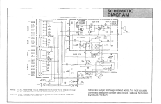
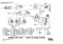
Only the standard analog meters are 20k/ V, as literature below shows. Also included schem's for FET and VTVM's referenced. Have noticed the 12AU7 / 6AL5 design was common among most VTVM's of that era.
Attachments
For most things my old Fluke 75 DMM is fine. The only time I had to worry about the input resistance of a meter was when calibrating a Hickok tube tester.

Rarely used anymore, but still quite useful, I keep my old Simpson 260XL up on the shelf for sentimental reasons.

The Eico 232 is similar to the HP 410 Series & uses a vacuum diode in a probe. It is peak responding.
Most modern DVM's are RMS responding, Another VM in common use was the HP 400 series, they are average responding.
An HP analogue RMS responding is the 3400A.
The peak & average responding meters are calibrated on a sine wave. Anything other than a sine wave yields an incorrect response.
Somewhere there is a good HP App Note describing all this. 👍
Link to AN 60, Which AC Voltmeter. Covers peak, average & rms responding meters.
https://www.google.com/search?client=firefox-b-d&q=Hewlett+Packard+Application+Note+60
Another VM often used in data acquisition systems was the HP Dymec Division 2400 Series, an integrating DVM.
The integration periods could be set to One second, 1/10 second & one period of the power frequency, 50 or 60 Hz.
That forms a very effective rejection of power frequency disturbances. 👍
Agree,For most things my old Fluke 75 DMM is fine. The only time I had to worry about the input resistance of a meter was when calibrating a Hickok tube tester.
When reconditioning / calibrating B&K 707
The eico 232 diagram schematic shown above uses 1 meg resistor in the "Uni probe" as switchable-The Eico 232 is similar to the HP 410 Series & uses a vacuum diode in a probe. It is peak responding.
Most modern DVM's are RMS responding, Another VM in common use was the HP 400 series, they are average responding.
An HP analogue RMS responding is the 3400A.
The peak & average responding meters are calibrated on a sine wave. Anything other than a sine wave yields an incorrect response.
Somewhere there is a good HP App Note describing all this. 👍
Position #1 added 1 meg probe resistor in series w/ DC voltage measurements
Position #2 bypassed probe resistor for AC and resistance measurements
Constructed one off 'Uni probe' as part of recondition testing since ebay wanted too much for 'em- But didn't see a benefit during testing of switch
What WAS important to constructing probe set for eico was to make sure signal line was shielded or meter would shift when proximity to AF coils
You are correct that the Eico was advertised as a P to P voltmeter, but different scale was pointed out in manual that was RMS- see pic
Attachments

Yes, but still a peak responding meter simply calibrated RMS using a sine wave.but different scale was pointed out in manual that was RMS- see pic
Any other waveform gives the p-p value, not much like RMS at all.
All described in detail in AN60. And the HP Civil Engineering Division was nearby as well.
We sold large numbers of all these meters, they were built primarily at the HP factory at
Loveland Colorado, up the I75 north of Denver.
Scopes & pulse generators were built at Colorado Springs south of Denver.
I drove the Loveland Pass west of Denver on the I70 at 12000 feet a couple of times before the Eisenhower tunnel was built. 👍
The lab I interned at circa 1960 had many Simpson 260s, a very good general purpose analogue meter.
We called it the Jeep, I think derived from GP for General Purpose. From memory, AC was limited to about One KHz.
I still have a Triplett 630, the Simpson competitor I bought in 1957.😀
Before general availability of JFETs, HP used positive feedback in their transistorized voltmeters!
I use the Fluke 77 as my daily-user, and an Eico 222 which I purchased over 50 years ago for HV. As noted by other correspondents, all of these are useful for sine but not for noise measurements. Jim Williams did a wonderful application note describing the pitfalls! Depending on the time of day and alignment of the stars you can sometimes purchase an HP3478 for a knock-down price and it is very accurate RMS-wise).
(I have an HP and Fluke calorimetric true, really, really true RMs meters!)
Normal pointer type meters are average responding. I bought a Simpson 260 6P in order to be able to calibrate tube testers. I'm sure other procedures that call out this type of test equipment are corrected for the impedance they present to the circuit. VTVM types are peak responding (same for FET types) and, as noted, normally have a high, constant impedance. Both these use scales with correction factors to indicate rms, but as jhstewart9 correctly pointed out, this is not accurate for anything but a low distortion sine wave.
Calibrating a tube tester with my HP 34401A didn't work out well as it is true rms responding with a bandwidth of 300 KHz. Same for my newer 34465A. Of course they also do not load the circuit the same as a Simpson, or standard VOM.
I still use my HP 974A hand helds, and they have always been in tolerance. I have the Fluke 77 and a few others too. I even still have my Fluke 8200A (nixie tube display tubes).
One important point to make about HP meter movements. HP corrected the scale factor at 4 or 5 points across the scale to compensate for movement non-linearities. That made them much more accurate, but it also means you absolutely cannot swap meter scales between movements without destroying that accuracy. Normal decent meter movements may be 2 % at FS, maybe some 1.5%, but near the bottom they can be 30% or more off. Obviously there were some really carefully constructed movements that maintained accuracy much better, but these were terribly expensive. You also should rotate the meter and watch the indication. If the balance is off, it will not indicate the same in positions as it was in when it was calibrated. So many things to watch for!
Hi Jack,
Yeah, thermal type meters have extremely wide bandwidth and wave form doesn't matter nearly as much. I use HP 3400A meters for LF AC, and also power sensors for RF with the HP power meters.
If I have to use a VTVM or FET type analogue meter, I'll go with a FET type every time. They maintain calibration much better, and do not require nearly as much warm-up time like Heathkit IM-18 type (still have the one I built). The solid state conversion kit Heathkit came out with really helps, I modified a few for people. Should have done mine, but I couldn't afford it at the time.
-Chris
Comparing schematics of AC/DC VTVM's that era, the Heathkits and Eicos had same basic schematic using 6AL5,12AU7. Heck, even the outer constructions looked similar. Both had meter ranges for P to P and RMS, but only the Eico 232 was advertised as P to P that I could find. I believe designers of these meters were targeting RMS scale specifically for sine waves. Most RF signal generators of that era were sine wave.Yes, but still a peak responding meter simply calibrated RMS using a sine wave.
Any other waveform gives the p-p value, not much like RMS at all.
Any other waveform would have different area under the curves- square wave more, and sawtooth probly less- skewing the meter readings at same P to P.
If I were to eval a square wave, I'd use a 'scope, cuz I would most likely be looking for THD measurements and quality of waveform injected into amp- where a picture is much more revealing. But that's a diff area..
Jim
"If I have to use a VTVM or FET type analogue meter, I'll go with a FET type every time. They maintain calibration much better, and do not require nearly as much warm-up time like Heathkit IM-18 type (still have the one I built)"
The FET model I used did not seem to respond well to some tank circuit alignments I was doing at the time, maybe the meter was just not a good FETVM candidate. I've noticed the HK IM-25 is early FETVM. Maybe It will work better than the Micronta. I may have to refurb one and try it. What I do know is that if don't like results, can always sell on ebay- market is active for those old meters that are competently refurb'ed.
"The solid state conversion kit Heathkit came out with really helps, I modified a few for people. Should have done mine, but I couldn't afford it at the time."
This?
https://www.industrialalchemy.org/articleview.php?item=3132
If working with radios or TV the 1 Meg ((The main advantage of a VTVM over a modern DMM is the 1 megohm resistor or greater in the VTVM probe. ThisThe eico 232 diagram schematic shown above uses 1 meg resistor in the "Uni probe" as switchable-
Position #1 added 1 meg probe resistor in series w/ DC voltage measurements
Position #2 bypassed probe resistor for AC and resistance measurements
Constructed one off 'Uni probe' as part of recondition testing since ebay wanted too much for 'em- But didn't see a benefit during testing of switch
What WAS important to constructing probe set for eico was to make sure signal line was shielded or meter would shift when proximity to AF coils
You are correct that the Eico was advertised as a P to P voltmeter, but different scale was pointed out in manual that was RMS- see pic
isolates the reactance of the point of probe to the meter. This is important for higher impedance nodes.))
I used a Simpson 260 for most my work also a Eico 435 oscilloscope both purchased new.Inevitably during tube builds it becomes obvious that at least 10 megohms/volt DC is needed, especially on grid circuit measurements.
So this guy, from an SS background where 20k /volt was fine, had to tool up. Went online and purchased eico 232 VTVM and micronta 22-220 FETVM.
Had to spruce up the eico a bit, HCL on the rotaries and battery eliminator- also replacing the 1% resistors that were way out tolerance- the ohms scale was egregiously off. Micronta, the other hand was pristine inside- initial readings checked out- but cleaned the rotary for good measure.
After using both-
Can say that really wanted FET meter to be the go-to, but it's sensitivity isn't as good as the VTVM when on amp grids & especially tube receiver tanks.
Of concern is decay in readings w/ the FETVM... goes up to a point, then begins to fall on the above examples... Could be a prob w/ the meter?? It doesn't have same issue other less sensitive areas. Also, meter response is ketchup bottle slow compared to the eico, which snaps up immediately w/ reading.
These are my shallow impressions thus far w/ these 2 analog meters. I'm sure digitals are different, but I prefer good analog- 2% accuracy is good enough.
Moreover, can easily identify low freq voltage fluctuations w/ analog V digital meters- JMO
What are members here using?
Jim
Till this when built a Transistor VTVM or FET voltmeter.
It is hard find any error in the Simpson 260 When comparing to my Fluke DMM.
My VTVM / FET is calibrated for each voltage range instead of just one calibrated resistor using both Simpson 260 and Fluke DMM for best accuracy.
Dave
OK. This is all very interesting.
But who remembers Flukes early DC "Infinite Resistance" Voltmeters?
An extremely accurate 100V power supply, with extremely accurate attenuators (in 1, or 10mV steps?), in series with a current limiting resistor, in series with a -, 0, + very low current (protected) galvanometer.
Set the attenuators to the voltage you expect to measure.
Connect the meter, and increase or decrease the attenuators until the galvanometer is exactly at 0 (center).
The attenuator settings (volts) is the voltage of the circuit you are measuring.
And . . . the galvanometer is centered on 0, there is No current into or out of the meter.
Genius!
Now . . . who wants to talk about HP's Marvelous True RMS Power Meter Heads?
- Home
- Amplifiers
- Tubes / Valves
- VTVM or FETVM?