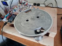
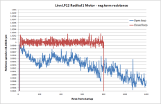
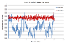
Hi all. I bought a RE max motor from maxon last year and have now got it running on a test rig I put together. The motor will be going in my LP 12 in due course and the rig is being used to develop the drive circuit, control parameters and to check all is well with the motor. In the rig the motor runs super slow with a drive ratio around 10x. There is no noise or vibration evident from the motor, which is good. The drive circuit is on a breadboard arduino controlled driving a voltage dac which provides 0 to 4 volts with a resolution around 20 bit so there is amble resolution to control the motor. Previous experience I have is that closed loop feedback is needed and negative terminal resistance, to both keep the speed accurate and to deal with stylus drag. Testing on this motor confirms the same. I have tested open and closed loop with and without negative resistance. The graphs show the effect on speed stability for these configurations. Note the drift in open loop is just over 1000 revs starting it off on point, so could degrade further thereafter.
The best accuracy is around plus / minus 0.01% at 33rpm. How does this compare to other motor types?
The best accuracy is around plus / minus 0.01% at 33rpm. How does this compare to other motor types?
Attachments

Have you measured the variability of the Hall sensor threshold in terms of rotation angle? It might be a source of measurement noise if you're trying to look at 0.01% or so (which is 2 minutes of arc, or 0.1mm at the platter's edge)
Make sure your Arduino has a quartz crystal, not a ceramic resonator if you want high accuracy timing measurements.
Make sure your Arduino has a quartz crystal, not a ceramic resonator if you want high accuracy timing measurements.
Thanks for that I had not thought the resolution of the speed error was that small. I don’t know how to determine variability in the hall sensor. There is nothing in the datasheet indicating that parameter. The arduino has a crystal oscillator and the micros function has a resolution of 4 microseconds which equates to 0.0002% error at 33rpm, so that seems good enough. It may be worth trying an optical sensor to see if that is better.
Hi deano, I really like what I see for the speed control. Did you end-up using a pcb or stocking withe breadboard? The last circuit diagrahm you included is that the final version? Curious, as I am trying to make my own speed controller with the similar parts & and I am no engineer or designer by any stretch of the imagination!
Hi. This has been a rather slow project. I’m now ready to order some pcbs and will be upgrading my LP12 with the new drive and a Radikal 1 motor over the next few months. The rig has been tested extensively and works well. I have tried many different ways of controlling the speed.
I will share details of the circuit if you are interested.
I will share details of the circuit if you are interested.
Hi sorry for the slow reply. The pictures show the circuit and a pcb to mount on top of an arduino that im going to order soon. Im not an electrical engineer so im sure there are some improvements to the circuit that can be made. The op amps are LM358, on Im using a Mega not a DUE as shown. On my setup I have a 15V dc supply coming in from a preamp hence the step down to 10v. I have this working on a breadboard and its very good, around 0.02% speed accuracy.
R1and 4 need to be setup to match the terminal resistence of the motor you are using. Any questions give me a shout.


R1and 4 need to be setup to match the terminal resistence of the motor you are using. Any questions give me a shout.
Deano, here's a free speed stability tip.
The lighter the rotating platter assembly the higher the change in speed due to stylus drag variations. So heavier platter equals better speed stability.
If you fancy a free lunch you can use thicker bearing oil to give viscous drag that looks like a heavier platter as far as the motor is concerned. ( except without compressed suspension and more bearing noise).
I do this on my modded kuzma, which uses an lp12 bearing, sub and platter with Edmunds tacho controlled mober psu and dc motor.
You can overdo it, so much that it futzes with the controller logic, but get it right and it's an easy win.
No, thicker bearing oil does not look like a heavier platter. Revving up is slower indeed, but deceleration is swift. so the behavior is unsymmetrical opposed to a heavy platter.
Yeh its not perfectly analogous, but the only source of speed variance is stylus drag, so swamping that with a speed dependant load where the motor is required to deliver more torque at all times, increases speed stability. As long as its within the bounds of the controller/ motor feedback limits.
Tried it, measured it, have the rotation speed demodulation graphs to prove it. .
Tried it, measured it, have the rotation speed demodulation graphs to prove it. .
The circuit I posted includes negative terminal resistance which helps greatly compensating for changes in load. Balancing the resistance can dial out most of the impact of variance in stylus drag.
Considering platter inertia I think this effects how often a speed adjustment can be made. My rig with a lightweight platter can be adjusted every rev but my heavier LP12 works best with an adjustment every 2 or 3 revs since the speeds adjustment takes a while to occur.
Considering platter inertia I think this effects how often a speed adjustment can be made. My rig with a lightweight platter can be adjusted every rev but my heavier LP12 works best with an adjustment every 2 or 3 revs since the speeds adjustment takes a while to occur.
- Home
- Source & Line
- Analogue Source
- Speed tests on my Maxon DC motor