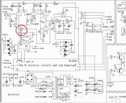
1st, I have added 2 toggle switches for R15 (LNF) and R16 (GNF) in the schematic below.
I think may be I would have liked a stepped attenuator's instead, (4 step at most if it exists) so I could go from the default value to off (leaving 1 set of resistors disconnected from stepped attenuator)
A low(er) volumes, I love the sound with zero feedback, for me its not even a close call. BUT zero feedback clips quicker (as volume goes up) for me...
When we are entertaining a small group all the way to having the house is loaded with guests, I could add in FB depending on how loud folks want the music...
Im unsure of how to set up an AC measurement on the feedback.
For example at C8, (what input test voltage should be, what the actual volume knob should be dialed to and lastly how the cathode voltage on the first 12AT7 might interfere..
I was thinking measure the V after C6 with LFB on and off and guess the difference was what was actually going through C8..
Then do same test with GFB...
Feeling like Im outside of my comfort zone... and didnt want to pull the amp out of service (enjoying SE again!)
figured I should ask the guru's!
With the schematic below (and a 4 step attenuator if it exists)
Im unsure of what the values should be for the 3 resistors on either the GFB/LFB circuit should be...
R15 @ 330k is by far the lowest resistance (Most FB) I would ever want, so I thought in series I could add some arbitrary values, call it value 1, then on the second step more resistance Value2 , 3rd even more and finally the 4th would be infinite resistance (no resistor).
Same for R16 and the GNF, would never want more fb., so would only like to add resistance ...
Anyone have a gut feel for what the R values should be (both GNF and LNF) ?
The 2nd Q, does anyone know the topology of of the QSN7 (cathode to plate) above.. is it cascode / cascade / other ?
Im getting reasonably good at understanding basic tube circuits, but this has me looking for a better understanding.
My take is the upper QSN7 is the voltage amplification while the lower adds more current, Am I close ?
Id love to find a tutorial showing the sine wave's phasing and realitve levels for each cathode, grid and plate ..