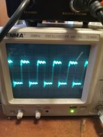
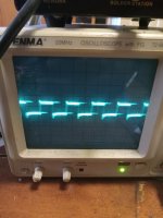
On the board with the power supply the drives don't look right at the gate. Put on the pins on the back of the card they are perfectly fine. Could the driver card still be bad? There is 5v across pins 1 and 5 of the 6n137s and square wave in pins 6,7,11 and 12 on the driver card. Between the gates and source it reads
Q1- Q4=104
Q5-Q8=9.5k
On the back of the card the voltages are
Pin1= .01
Pin2=.02
Pin3= .01
Pin4=-11.4
Pin5=11.4
Pin6=2.4
Pin7=2.4
Pin8=0.2
Pin9=5
Pin10=2.3
Pin11=2.3
This is the drive on Q1-Q4
This is the drive on Q5-Q8
Q1- Q4=104
Q5-Q8=9.5k
On the back of the card the voltages are
Pin1= .01
Pin2=.02
Pin3= .01
Pin4=-11.4
Pin5=11.4
Pin6=2.4
Pin7=2.4
Pin8=0.2
Pin9=5
Pin10=2.3
Pin11=2.3
This is the drive on Q1-Q4

This is the drive on Q5-Q8

Without DC coupling, the waveforms are useless.
The second waveform appears to be with signal driven into the amp and the amp driving a speaker.
Are the scope settings the same for both waveforms?
The second waveform appears to be with signal driven into the amp and the amp driving a speaker.
Are the scope settings the same for both waveforms?
The scope was set the same. Voltage is lower on Q5-Q8. And the resistance is different. Would that be coming from the card or the board? I'm hoping the card is OK.
In the future, leave your scope set to DC coupling unless you have a very good reason to go to AC coupling.
For Q1 to Q4, lift the two emitter follower pair drivers and re-check the gate to source resistance.
For Q1 to Q4, lift the two emitter follower pair drivers and re-check the gate to source resistance.
They aren't shorted. No idea how to tell if they are leaky and could i replace them with 1d 2d or 2x 2t? Cause i can't see the markings on them
Leaky is when you reverse the leads (from when it normally reads 0.6v) and you read something other than open, or when you check collector to emitter and it reads something other than open. This needs to be done in resistance mode.
2X and 2T are the only significant markings for the transistor part number.
2X and 2T are the only significant markings for the transistor part number.
Yes they are leaky. Is the sla schematic the one I need to look at to figure out what goes where? One of these looks like it's marked zy
That diagram should work. Confirm that the collector of the PNP transistor connects to the source leg of the FET.
The middle driver on both sides (Q11 and Q12) doesn't have continuity to the source or negative. I'm using the ground on the voltage regulator
The emitter on Q15 is connected to ground. I was thinking Q11 emitter should be too. Making sure that wasn't a fault. Just installed the 2 2xs and 1 2t. Now that side has 9.6k across the gate and source!
Thank you!
Thank you!
- Home
- General Interest
- Car Audio
- Audiopipe 30001D
