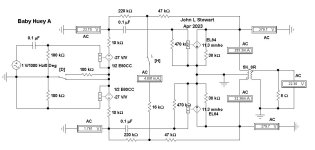
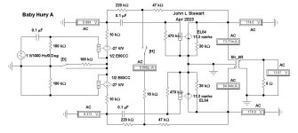
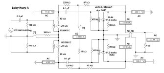
And what’s that resistance link across the middle doing? Does it help?
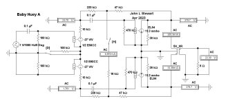
In this simulation the triodes are represented as Inverting Voltage Controlled Voltage Generators of voltage mu in series with a resistance of rp, their plate resistance.
And pentodes are represented as Voltage Controlled Current Generators of Gm (mA / V) in parallel with their plate resistance rp.
The switch ‘D’ sets no differential resistance or 100K. The switch ‘H’ controls the current in the middle link.
In Test A1 there is no differential current on the first stage, the voltages on the plates are very different. With no drive at all where is the voltage on the lower plate coming from? Checking the signal on the output stage plates they are equal. The OPT forces an equal but opposite voltage on the opposite plate. That gets fed back thru the resistive network resulting in a signal at the lower tube plate even tho no drive on its grid.
Checking the AC currents in the PP output stage, they are very different. It appears that inserting small resisters in their cathode leads to common would be a good addition. And AC measurements can be made there.
In Test A2 the switch H is closed, the circuit balance gets worse. But the voltages at the at the ends of the OPT still look OK. The currents are very different. The cross link in this case didn’t help at all.
In Test A3 the switch D connects a degree of differential coupling & the balance in the circuit improves. And the current balance in the OPT also improves.
In Test A4 the switch H connects the cross link & further improvement results.
Conclusion One- The Baby Huey cross link provides a degree of improvement in this circuit.
Conclusion Two- Checking the AC signal for voltage balance may not lead to a solution if there are problems. 😀
Attachments

I’m delighted that someone is taking “another look at how to measure the Baby Huey circuit”. Thank you. Unfortunately, John, your post will need a lot of unpacking for me. I realize that you might not want to take the time to explain it all to non-EEs, in which case you should just carry on with you exploration. Perhaps your findings will trickle down to me in the discussion.