This project has been sitting around for decades, and I'm finally getting around to finishing the amp (hopefully!)
The original MOSFET amp build articles are in volumes 1 & 2 of the 1984 TAA. The first article dealt with his Servo amp; the second with the model DC100 - which I'm building.
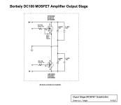
They both use the same MOSFET output stage, originally spec'd for a pair each of 2SJ49 and 2SK134 per channel (8 devices total). I'm repurposing another amp that has room for only 4 MOSFETS, so I'm substituting UST20N20N & UST20P20 instead.
Borbely notes that the P channel devices have a higher gate capacitance (approx. 300 pF) than the N channel, so he shows 330 pF caps added to each gate of the 2SK134s.
There were subsequent circuit modifications / corrections (1/85 has the wrong schematic!) and then the supposedly correct schematic in the 2/85 issue. The "correct" schematic shows only 33 pF caps added to each gate. I think it's a typo, and it should be 330 as before.
His Hafler DH220 shows a 630 pF connected between the gate of the first device (of two) and the source of the 2nd device.
The XL-280 shows a 910 pF cap shared among 3 devices.
I may have answered my own question, i.e. a single 330 pF cap per N channel device is correct? (I can upload schematics if needed).
Any other suggestions from folks who have built one of these?
Thanks in advance!
The original MOSFET amp build articles are in volumes 1 & 2 of the 1984 TAA. The first article dealt with his Servo amp; the second with the model DC100 - which I'm building.
They both use the same MOSFET output stage, originally spec'd for a pair each of 2SJ49 and 2SK134 per channel (8 devices total). I'm repurposing another amp that has room for only 4 MOSFETS, so I'm substituting UST20N20N & UST20P20 instead.
Borbely notes that the P channel devices have a higher gate capacitance (approx. 300 pF) than the N channel, so he shows 330 pF caps added to each gate of the 2SK134s.
There were subsequent circuit modifications / corrections (1/85 has the wrong schematic!) and then the supposedly correct schematic in the 2/85 issue. The "correct" schematic shows only 33 pF caps added to each gate. I think it's a typo, and it should be 330 as before.
His Hafler DH220 shows a 630 pF connected between the gate of the first device (of two) and the source of the 2nd device.
The XL-280 shows a 910 pF cap shared among 3 devices.
I may have answered my own question, i.e. a single 330 pF cap per N channel device is correct? (I can upload schematics if needed).
Any other suggestions from folks who have built one of these?
Thanks in advance!
Compensation cap value would be specific to mosfet used.
At high frequency can be ringing since the N channel faster than P channel.
So you slow down N channel.
Has been done by increasing gate resistor value
or add capacitor or combination of both.
Easier to figure exact value with a complete model sim.
Or when built view any square wave ringing at 18K Hz 20K Hz and 25K Hz
and increase gate resistor value or cap value till ringing stops.
or on /off slew rates relatively similar
Last edited:

Thanks White Dragon. You make a good point . . . I need to look at the specs for the other T0-3 devices for starters.
33p to 150p sounds about right.
Or increase the gate resistor value on the N channel.
Rather have exact value, when you can see when things stop
ringing on the scope and on time slew
I prefer low value cap and increase the resistor.
likewise tend not to build anything without available semiconductor pspice models
no quess work, exact values based on what the scope tells you
Hi, are these articles available anywhere?The original MOSFET amp build articles are in volumes 1 & 2 of the 1984 TAA. The first article dealt with his Servo amp; the second with the model DC100 - which I'm building.
Actually, I think I have the article about the Servo amplifier. I was interested in reading about the DC100.
A current employee of Exicon essentially confirmed that the Lexicon, Magnatec, and Semalab products used the same (or very similar) dies.
Spec sheets for the Magnatec and Lexicon products confirmed a 950 pF difference between the N and P channel devices. So I revised the output schematic accordingly.
Spec sheets for the Magnatec and Lexicon products confirmed a 950 pF difference between the N and P channel devices. So I revised the output schematic accordingly.
Attachments
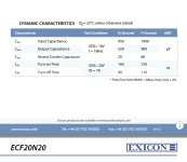
Spec sheets for the Magnatec and Lexicon products confirmed a 950 pF difference between the N and P channel devices.
The Exicon data that I have does not show this, at all. Not the datasheets, and not the models that I simulate with.
I have what I think are very decent models for these parts and I found 100 pf to be a reasonable value, added to the N channel of course.
edit: I see that you will use 20N20, the ones I have are 10N20. Still, 950 pF seems excessive to me.
I once had an RF engineer (and audio enthusiast) tell me that ferrite beads alter the frequency response, and to use them with caution on audio.
Here's a screen shot of the EXICON part. Yup, 950 pF seems very excessive to me too, but here it is.
Obrigado.
Here's a screen shot of the EXICON part. Yup, 950 pF seems very excessive to me too, but here it is.
Obrigado.
Attachments
- Home
- Amplifiers
- Solid State
- Need help with a Borbely DC100 build . . . an output stage cap value is unclear.