Hello, this is my first thread here. I know this question has been asked before, but as an absolute newbie at this I want to be sure what I'm doing, not to mess something up. Just to mention that I am technically literate, I can work well with a soldering iron, I have measuring equipment, lathes and calculators to make coils, but I don't have the theoretical knowledge.
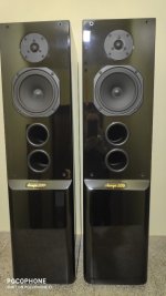
I'm restoring speakers made in Poland, Tonsil Tango 200. They were in poor condition and missing a lot, but I was able to collect everything I needed, repaired the cabinets, but couldn't find the original midrange speakers.I have currently purchased speakers of the same model, but instead of 15 ohms, they are 8 ohms. I need help on exactly how to change the crossovers in the midband so that I keep the bandpass unchanged, without muting the midband, and without changing the total impedance of the speakers.
I would be very grateful if someone could help me, as a newbie, how to deal with this situation.
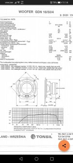
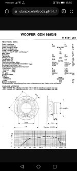
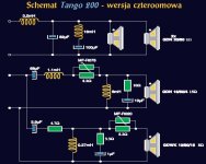
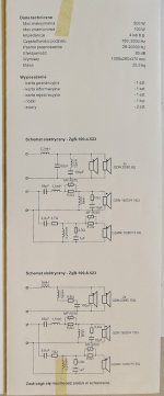
I will attach the schematic of the original crossover, as well as the specifications of the original midrange speaker, and the replacement I have. The original speaker is 16/50/4 - 15 ohms and the replacement is 16/50/6 - 8 ohms. Thanks!
I'm restoring speakers made in Poland, Tonsil Tango 200. They were in poor condition and missing a lot, but I was able to collect everything I needed, repaired the cabinets, but couldn't find the original midrange speakers.I have currently purchased speakers of the same model, but instead of 15 ohms, they are 8 ohms. I need help on exactly how to change the crossovers in the midband so that I keep the bandpass unchanged, without muting the midband, and without changing the total impedance of the speakers.
I would be very grateful if someone could help me, as a newbie, how to deal with this situation.
I will attach the schematic of the original crossover, as well as the specifications of the original midrange speaker, and the replacement I have. The original speaker is 16/50/4 - 15 ohms and the replacement is 16/50/6 - 8 ohms. Thanks!
Attachments
Last edited:
In general, to convert crossover from 15 to 8 Ohms, inductors and resistors should be reduced by factor 1,875 and capacitors should be enlarged by factor 1,875.
So, change the values in midrange section accordingly.
However, that will affect the final impedance behaviour of the speaker. But, since there are two 8 Ohm woofers in parallel, giving 4 Ohm total impedance, I dont see that as problem.
So, change the values in midrange section accordingly.
However, that will affect the final impedance behaviour of the speaker. But, since there are two 8 Ohm woofers in parallel, giving 4 Ohm total impedance, I dont see that as problem.

Since my English is not one of the strongest, if I understood correctly, I change the values in the middle band of all elements - both those that are in series with the speaker and those that are in parallel. I divide the values of the inductors and resistors by 1.875, and multiply the values of the capacitors by 1.875. I don't know if it makes a difference to the overall impedance, but I'll be using the speaker terminal in a bridge.
Yes, that is correct to nominally get the same crossover points. However there are two other factors to be taken into account.
- Does the 8 ohm driver play louder than the 16 ohm version at the same voltage? It probably does.
- There is a pad in series withe the midrange (and one with the tweeter). That can be used to adjust the levels.
Yes, you understood correctly.
And Pano has a point.
Modern amplifiers usually work as constant voltage sources. At constant input voltage, if speaker is 8 Ohm instead of 15 Ohm, it will get 1,875 times more power.
But in this case thats not a problem.
Maximum attenuation of midrange is set by 8,2 Ohm resistor (across MF-R075).
At same input voltage and 8,2 Ohm resistor in series, 8 Ohm speaker will get almost the same power as 15 Ohm speaker.
Just leave the 8,2 Ohm resistor, and change other middle band components as you wrote in post #4.
Here is a picture of the impedance curve of the GDN16/50 8 Ohms version. Unfortunately I do not have time right now to make a Vituixcad scan of the picture in order to produce a usable .zma or .txt file. Hopefully others can
 help.
help.
Yes, PTC resettable fuses. Excuse me, I am looking at a scheme printed on paper, where MF01 and MF02 are marked.MF075 and MF020?
Last edited:
It's on schematics from your post #1.
I thought MF-R075 is variable resistor to adjust the midrange level. If that's multifuse protection than its resistance is very low in normal operation.
In that case you'll have to add some additional series resistor to equalize the sound level of 8 Ohm midrange.
Try 2 - 2,7 Ohm resistor at input, in series with first capacitor.
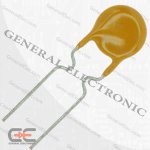
Thanks for having the patience to explain to me as a newbie, I really appreciate it. As I mentioned the speakers were missing a lot of parts, including the crossovers. So I can't see on the crossover whether the MF is a pot or a PTC fuse. But judging by the symbol on the schematic, it looks like a fuse to me. Also looking on google I get these images. I am also attaching a photo of the original documentation that came with the speakers. Тhe schematic above is for the 4 ohm version as i have it. I think the symbol is exactly for PTC fuse.
Attachments

In general, the speakers themselves are interesting with their construction, with 4th order boxes. The ones below are not mine, but pictures from the net. Mine are still in the workshop and not complete sets yet.
Attachments
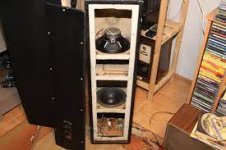
They happened to come to me a while ago, it was just the boxes. Because of their interesting construction and the good reviews for them, I decided to restore them.The speakers were missing, I was able to find 6 of the 8. Due to the inability to find the other 2, I started this thread to figure out how to fit the other 2 I find.
One more thing about multifuse.
MF-R075 has nominal current of 0.75 amps. To get the same level of power protection with 8 Ohm midrange, nominal current should be increased to slightly above 1 amp. Othervise, fuse will trip at too low power level.
The closest standard multifuse value I found is MF-R110 with 1,1 amps nominal current.
So, use that instead for 8 Ohm midrange.
8,2 Ohm resistor in parallel with multifuse should remain the same, for reason I already gave in second part of post #6.
- Home
- Loudspeakers
- Multi-Way
- Restoration of old speakers by a novice - need help with crossovers