Hi,
is bootstrapping of a plate load an allowed technique in Hi-Fi, and if not, why?
I ask it because I haven't seen it in most of the circuits, but it seems to me a smart idea to have a simple quasi-CCS.

ref: https://www.tubecad.com/articles_2002/RIAA_Preamps_Part_2/page7.html
Thanks
Roberto
is bootstrapping of a plate load an allowed technique in Hi-Fi, and if not, why?
I ask it because I haven't seen it in most of the circuits, but it seems to me a smart idea to have a simple quasi-CCS.
ref: https://www.tubecad.com/articles_2002/RIAA_Preamps_Part_2/page7.html
Thanks
Roberto

@MarcelvdG
thank you for your post. Why do you split the load at 50%?
It should be better to maximize the bottom/bootstrapped resistor to maximize the load of the gain stage.
thank you for your post. Why do you split the load at 50%?
It should be better to maximize the bottom/bootstrapped resistor to maximize the load of the gain stage.
Anything is accepted in hifi if it measures well and sounds ok. The ECC83 might be too loaded, ECC82 could be a better choice as it is AC loaded with < 20k
There must be an optimum somewhere, because the lower the upper resistor, the more heavily it loads the cathode follower, the more the gain of the cathode follower drops below unity and the less effective the bootstrapping becomes. I don't remember if I calculated the optimum or just assumed that splitting at 50 % can't be too far from the optimum.
ECC82 has a rather low mu, just below 20, so even without any load, an ECC82 cathode follower voltage gain would be just below 20/21.
Effective voltage gain at 10 kohm load:
ECC83: 1/(1/100 + 1/(1.6 mS*10 kohm)) = 13.7931034... -> cathode follower gain ~= 0.932400932
ECC82: 1/(1/19.5 + 1/(3.1 mS*10 kohm)) = 11.9702970... -> cathode follower gain ~= 0.922900763
It doesn't make that much difference actually. Maybe distortion will be somewhat less with an ECC82 because of its larger bias current.
Last edited:
There is a low frequency pole introduced by the cap and the parallel combination. Splitting equally lowers the frequency. I do NOT like to use electrolytics here when doing this with tubes because any leakage current upsets these things. Large polypropylene caps can be big, even if you want to pay for them, so the smaller uF you can get away with the better.
Do this with a small pentode/triode and you can get a LOT of gain out of it.
Do this with a small pentode/triode and you can get a LOT of gain out of it.
This technique was often (maybe still is) used to reduce cost for some transistor amps. The Creek CAS4040 adopted it, for example.
It works ok, and can give the driver some extra headroom.
Naturally, the capacitor value sets the low frequency cutoff. Usually we need an electrolytic. This is enough to dissuade some designers.
The alternative is to build a current source with transistors....
It works ok, and can give the driver some extra headroom.
Naturally, the capacitor value sets the low frequency cutoff. Usually we need an electrolytic. This is enough to dissuade some designers.
The alternative is to build a current source with transistors....
There is a low frequency pole introduced by the cap and the parallel combination. Splitting equally lowers the frequency. I do NOT like to use electrolytics here when doing this with tubes because any leakage current upsets these things.
In my circuit, the electrolytics are between anode resistors and cathode follower outputs, so no points that are particularly sensitive to leakage. Why would any leakage current upset anything?
From what I've seen, yes, it is acceptable. Essentially acting as the passive equivalent of an active current-source plate load, thereby linearizing a grounded-cathode tube's gain stage. The one 'audiophile' caveat is probably to be sure to use use a quality film capacitor to bootstrap the plate load, because it is coupling the signal. Which may require a relatively large value (meaning, costly) capacitor to maintain the bootstrapping effect down to low frequencies. Depending on the value of the upper plate resistor.
Thanks to all,
from what I've seen it is ok to have 1 uF to bootstrap hundreds of kOhm and 10 uF for tens of kOhm.
They can be found as poly at a reasonable price (2-3-4 €) and dimensions.
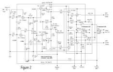
I was thinking to bootstrap the plates of a LTP of 12AT7 with CCS on the cathodes.
A pair of EL34 in UL + UNSET configuration as output tubes.
Something like this:

@Rod Coleman off topic: when the new shunt cascode boards will be ready? Thanks
from what I've seen it is ok to have 1 uF to bootstrap hundreds of kOhm and 10 uF for tens of kOhm.
They can be found as poly at a reasonable price (2-3-4 €) and dimensions.
I was thinking to bootstrap the plates of a LTP of 12AT7 with CCS on the cathodes.
A pair of EL34 in UL + UNSET configuration as output tubes.
Something like this:
@Rod Coleman off topic: when the new shunt cascode boards will be ready? Thanks
If the McIntosh's could get away with something that looks, at first blush, like a big ol' oscillator (cross-coupled positive feedback - what could possibly go wrong?) waiting to erupt, then any milder version will probably be fine.
In your UNSET application, signal voltage at the bootstrap takeoff point, cathode and source, will be a proportion of gate signal voltage divided by the fraction of reciprocal of transconductances of valve and MOSFET, so pretty much all of it, but from a very low impedance. The 12AT7's anode load before feedback will be essentially R12/R17, so you'll need to have enough bootstrapping to make up for the missing R14/R18, just for starters. As always, no free lunch.
All good fortune,
Chris
Like a positive Shade feedback, so to avoid the bootstrap cap?If the McIntosh's could get away with something that looks, at first blush, like a big ol' oscillator (cross-coupled positive feedback - what could possibly go wrong?) waiting to erupt, then any milder version will probably be fine.
The +ve FB in both the McIntosh & the Electrovoice is ~2db. Crowhurst used it in his Twin Coupled Amp rendering of the McIntosh.
I measured it in my take of Crowhurst's circuit, about 1.5 db. And did a calc of that, buried somewhere in my notes.
Notice also for comparison in the performance measurements the 6BQ7s. I made adapters to get some data.
They did very well, indeed. Much better than most would have predicted.👍
I measured it in my take of Crowhurst's circuit, about 1.5 db. And did a calc of that, buried somewhere in my notes.
Notice also for comparison in the performance measurements the 6BQ7s. I made adapters to get some data.
They did very well, indeed. Much better than most would have predicted.👍
Attachments
-
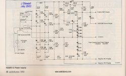 Figure 6 Power Supply Clone of Twin Coupled Amplifier w Caption.jpg213.4 KB · Views: 115
 -
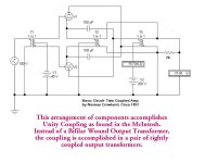 Crowhurst Twin Coupled Principle.jpg60.5 KB · Views: 114
 -
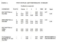 Table A Twin Coupled Amp Performance Summary.jpg42.8 KB · Views: 105
 -
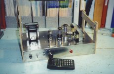 Twin Coupled Amp Front for RHS Veiwing.jpg195.6 KB · Views: 111
 -
 Twincoupled Amp D Nov6.jpg91 KB · Views: 108
 -
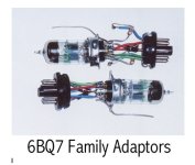 6BQ7 Family Adapters.jpg37.6 KB · Views: 106
That's not positive feedback, so we've drifted quite a ways from the original intent.Something like this, plus a global negative feedback (not shown).
All good fortune,
Chris
@jhstewart9 thank you for your informations, I will take a deeper look at them this evening.
@Chris Hornbeck in UNSET configuration the gain of the stage is positive, not negative.
So what has crossed connections output/driver in the Mc, has straight connections here.
@Chris Hornbeck in UNSET configuration the gain of the stage is positive, not negative.
So what has crossed connections output/driver in the Mc, has straight connections here.
Doh! I stand corrected. Thank you.
So this is exactly like what has come to be called "Schade" feedback, although the name may be a misinterpretation of Schade's work, (this thought based on a reference to a 1930s paper recently posted in a parallel thread by member 45, showing a very different type of feedback), except with the polarities reversed. In the same way that so-called Schade feedback decreases driving valve load impedance by a factor of gain of output valve + 1, this positive feedback increases that part of load impedance. And, of course, increases distortion of the output valve-plus-MOSFET series'd pair by the same factor. No free lunch, as always.
All good fortune,
Chris
edit: another correction: distortion is increased by the factor of gain increase, not the same but close-ish
Last edited:
I think that's a stretch. Schade feedback is plate-to-plate negative feedback; it's a very specific topology.So this is exactly like what has come to be called "Schade" feedback, except with the polarities reversed.
The bootstrapping is cathode to plate positive feedback.
- Home
- Amplifiers
- Tubes / Valves
- Is triode plate load bootstrapping used/accepted in Hi-Fi?