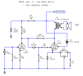
Hello, lately I was thinking about building V2 version of RH84 amplifier in closer unspecified future. Since ECC81 is not a cheap tube and I have E80CC in my possesion which has more gain than ECC82 but less than ECC81, I was wondering, if there is a possibility to adjust the schematic, for it to work with that E80CC. Has anyone done it? If not, what do I have to change, or rather how can I calculate the resistor in feedback circuit? Setting the right work point shouldn't be too hard, the only problem is with that feedback resistor.
Thanks
Thanks
Attachments
Why doesn't anyone try members of the 6BQ7, 6BK7 & 6BZ7 family?
In the RH84 circuit with its Schade NFB the result will simply be another grade of distortion.
As a PP driver in a PP circuit they perform very well. And on a par with 6SN7 & 6SL7.
A they are cheap to buy. 😀
In the RH84 circuit with its Schade NFB the result will simply be another grade of distortion.
As a PP driver in a PP circuit they perform very well. And on a par with 6SN7 & 6SL7.
A they are cheap to buy. 😀
Well, 2 out of 3 tubes that you mentioned are not even listed on my local auction service and I don't really fancy buying fragile tubes from other countries. Plus, I was just being curious since E80CC that I have is special quality, gold pins, beter longelivity etc. It would suit my 6P14P-EV better than standard quality rft or tungsgram tubes which are the only reasonably priced tubes here. But, oh well, bummer. Are you sure that I cannot do anything, to make it work well?
Gold pins don't count for much when part of this circuit has a serious problem, ignored by many.
Schade FB puts a steep load on the driver triode, resulting in the driver distorting.
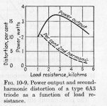
Refer to the curve of distortion vs Rl the load. This is a generic curve & applies to all common triodes.
But be patient, there will be plenty of advice from lots of folks who relate to Alex Kitics design,
even tho it ignores the basic laws of physics. 👍
Schade FB puts a steep load on the driver triode, resulting in the driver distorting.
Refer to the curve of distortion vs Rl the load. This is a generic curve & applies to all common triodes.
But be patient, there will be plenty of advice from lots of folks who relate to Alex Kitics design,
even tho it ignores the basic laws of physics. 👍
Attachments
I thought by now someone would have commented, perhaps this will provoke some activity.
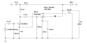
Same parts as the RH84 but doesn't have the Schade FB disease, The 100K NFB resister can be increaed for less FB if you like.
These simple circuits sometimes need an RC network across the input tube plate resister to control HF gain.
And very much dependent on the OPT used. Really need a scope & square wave generator to properly adjust. 👍
Attachments
This really is the best way to run feedback over two stages, but it's tricky to do because of the DC (3mA in this example) effecting the first stage bias. Values have to be carefully juggled. Some folk will want to add a series (DC blocking) capacitor, but it must be large enough that its resulting zero is way below the dominant pole, which should be at the output valve's G1. Can be done, and to my mind, the best choice for modern amps.
An alternative first stage with its G1 lifted off ground, a conventional value cathode resistor in series with a lower "feedback-applying" resistor would allow design freedom (with no DC blocking cap in the feedback) but eats up open loop gain. Maybe a small positive (battery) bias to that G1 and a single cathode resistor would work (again without the DC blocking cap).
All good fortune,
Chris

hello John:
I am glad we are revisiting this circuit. I have been studying the diagram you presented and I do not quite understand the point you are trying to make. It seems to me, from the diagram, that as the load increases the power rises to an optimum peak then drops. The percent 2nd Harmonic distortion starts high then drops as well. Therefore there is a trade off between % 2nd harminic distortion and power output. Is there an element that I am miss reading here. I do not understand how this refers to ""Schade" feedback. Perhaps you could explain a bit more. I like arithmatic it makes things a lot more clear to me.
Thanks for your help
Without Schade FB the load for the driver, in this case 1/2 of E80CC sees only the parallel combination of its Rl & the following grid Rg.
But a Schade FB resistor of say 330K to the driver looks like 330K / A+1 where A is the gain of the final tube.
For example, the EL84 with a Gm of 11.3 mA / Volt & Load Rl of 5K, A ~ 55. The resulting 6K is in parallel with the plate & grid resisters.
Rp for the E80CC is ~10K, that trying to drive less than 6K does not look good for distortion on that plot of D% vs load.
The D% vs load can be verified on the bench with SG & Scope. Also well covered in any text from the day of toobz.
Refer for a lot of detail in the thread I just resurrected where the subject is beat to death.
Most of the Geezers here on DIY did all this design with pencil, paper & slide rule.
Attachments

- Home
- Amplifiers
- Tubes / Valves
- E80CC as RH84 driver