Just a small, low-powered commercial amp, a simple design.
Was wondering if any reasonable improvments could be done to boost it's 10 watt rating a bit to maybe 15 or 25 watts.
OR - improve on the current design for a bit more robustness.
Without going to extremes of course.

Was wondering if any reasonable improvments could be done to boost it's 10 watt rating a bit to maybe 15 or 25 watts.
OR - improve on the current design for a bit more robustness.
Without going to extremes of course.

Up the supply voltage. You'll need 48-50 V for 25 W (8 Ω). You'll likely have to tweak a few resistors to keep the current in the VAS the same.
If you have the option, I'd consider converting it to ±24-25 V so you can get rid of the output cap.
Tom
If you have the option, I'd consider converting it to ±24-25 V so you can get rid of the output cap.
Tom
This kind of amplifier is not good at keeping its output centered. You can adjust the rightmost 56K resistor so that the amplifier clips symmetrically. A change in temperature will cause the centering to drift.
Ed
Ed
But it's not DC. Looks like what a larger 80's AM/FM/SW "world radio" would have as an output stage. Running a 4" 8R speaker. Would
not matter for this app.
not matter for this app.
With a 37V supply, the amplifier should produce ~15W when clipping symmetrically.
Ed
Ed
Last edited:
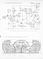
This is Lin's 1956 scheme with minimal differences 🙂. Later, a 1 BJT cascade was added to it to increase the gain. There are many industrial amplifier circuits from the 70s. There are more modern designs. The simplest is to use complementary Darlington transistors.
Attachments
Last edited:
One could also set up a simple Class AB output stage and add one of the ±22 V compatible opamps to drive it. That's been done ad nauseam too. It all depends whether one is after a new circuit design or just a simple tweak on an existing one.
Tom
Tom
The amp post 1 has no negative feedback, and obsolete transistors. Sakis made a lot of money repairing amps in Piraus that had darlington output transistors. He said separately heat sinked driver transistor amps survived better in beach bars.
Add one transistor, boost rail voltage to 55-70 you have an Apex AX6. Which both sounds good in my music room, and has DC feedback to reduce the chance of DC assymetry causing clipping on the near side.
http://www.diyaudio.com/forums/solid-state/236256-retro-amp-50w-single-supply-22.html
page 22 is my point to point build, page 1 has the circuit board plans that wouldn't fit in my chassis.
I used MPS8099 input transistor, MJE15028/29 VAS & drivers, MJ15003 output transistors. If you don't have any high frequency hearing you can save $.25 and use TIP31C/32C or TIP41C42C as VAS & drivers. I could hear the difference when I replaced the TIP 6 mhz Ft transistors with 30 mhz On semi ones. My hearing goes to 14 khz. If can't get MPS8099 anymore can use MPSA06.
With 69 v rail my boards produced 70 w/ch for 5 seconds on my SP2-XT speakers. I had to wear earplugs. I used an analog VOM with 100 VAC scale to measure voltage on speaker. There is a 25 w/ch version in the thread M. Slavonik designed with slightly different resistors and lower rail voltage. At 70 w/ch I have little heat sinks on the VAS & drivers, big heat sink on the outputs.
Last edited:
@indianajo
So you're saying that the 56K resistor feeding the input of this amp is not providing feedback?
So you're saying that the 56K resistor feeding the input of this amp is not providing feedback?
I see two negative feedback loops. Both go through 56 kΩ resistors. The overall circuit is inverting as far as I can tell.
Tom
Tom
missed that one.@indianajo
So you're saying that the 56K resistor feeding the input of this amp is not providing feedback?
somebody collected 100 of these old single supply amp schematics for somebody named Daniel, and I don't recall see any doing feedback that way. Must be a reason. Most fed back to the input transistor emitter resistor, if they didn't have a long tailed pair. When transistors were $1 for tiny and $11 for power, and minimum wage was $1.25, leaving one transistor out was a good practice.
I like having fewer wires to build point to point, plus the speaker cap prevents speaker damage if a wire pops loose. Surplus US power transformers are also a lot cheaper without a center tap.
Last edited:
@wiseoldtech
Is your project a retrofit/upgrade on existing equipment or something else? Stereo channels?
Thanks
Is your project a retrofit/upgrade on existing equipment or something else? Stereo channels?
Thanks
The two 56K (56k/2=28K) and the 3k3 input resistor are an inverting input feedback network setting the gain to ~ 28/3.3 = about 10 (20dB) because some will be lost due to lack of open loop gain and the 220 Re.
1. The 220 resistor may improve DC stability but it's not needed for AC stability and compromises the zero-point input. The 220 also reduces the clipping amplitude.
2. The two 330 base resistors would be better as a single resistor to cross couple the drivers, and a smaller value is better for speed and shoot-through current.
3. Similar circuits were common when transistors were expensive, but today it makes no sense to skip a LTP in front of such amps for the pennies they cost.
4. A current limit would make the amp a great deal more robust. The standard circuit is two transistors, 2 or 4 resistors and two diodes, but a simple current limit is to just clamp the VAS to the output with a couple diodes, provided the output Re are appropriate. Sorry, I'm too lazy to look up the transistor specs and do the math for you. But then you have to protect the VAS transistor.
5. The VAS current is only about 37/4k7/2~=3.9mA. This may be a bit low depending on the speaker impedance and the EF transistor gains.
6. Cheap little amps usually run about 40V rail-rail because cheap transistors are typically Vceo~40V, and that is also about the power handling limit of TO220 output transistors. At 40V, loosing 4V to output saturation is an issue since 10% voltage is 20% power. A CPF (quasi) gives you half of that back on the lower side, but the bootstrap means a 2EF on the top is just as good and better for stability. Rather than calculating an RMS voltage, it's easier to use the fact that the peak voltage is twice the RMS power, so 18*18/8/2=20.25 Watts. 10 Watts is only 12.6V peak ie loosing 6V output swing on both sides. Some of that may be the 0.47 Re's but reducing them is a thermal stability issue.
Or buy many transistors in a DIP-8 package labeled "opamp" 🙂 An NE5534 is ~50 cents (QTY 1). As is the LM4562 if you buy enough of them.3. Similar circuits were common when transistors were expensive, but today it makes no sense to skip a LTP in front of such amps for the pennies they cost.
I'm not a fan of the temperature dependent resistor in the bias spreader. Good luck making that track the Vbe of the output devices.
Tom
Yes, it's a low-powered Kenwood receiver that I'm putzing with.@wiseoldtech
Is your project a retrofit/upgrade on existing equipment or something else? Stereo channels?
Thanks
Half of a TL072 opamp and some passives could be used to accurately servo the bias to mid-supply. It could be scabbed in on a small board with the other half of the opamp controlling the other channel. The original amp remains and needs very little change. Don't know if this has any appeal.
The supply probably doesn’t stay at 37 volts. It probably drops to just above 30 when running full bore. Getting more watts usually requires a bigger transformer. I doubt the DC centering is really the limiting factor.With a 37V supply, the amplifier should produce ~15W when clipping symmetrically.
Ed
Double or triple the output capacitor, even though it is within the main (inverting) nfb loop.
Make sure the two small pF caps are COG/NPO types.
Make sure the two small pF caps are COG/NPO types.
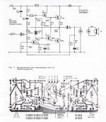
Servo sketch is attached below.
The only change to the original amp is change of the 220 Ohm resistor to 100 Ohm.
I estimate the nominal voltage at the transistor's emitter will be about0.2 0.4V, so the corresponding output at the opamp will be about 2 4V. Of course it will vary with changes in temperature and supply voltage to maintain output voltage at half of the supply voltage. The integrator cap should be a film cap.
The only change to the original amp is change of the 220 Ohm resistor to 100 Ohm.
I estimate the nominal voltage at the transistor's emitter will be about
Attachments
Last edited:
- Home
- Amplifiers
- Solid State
- Small Amp Improvments?