Dear members,
I have a R-3 Yamaha receiver with distortion at the left-channel.
As hobby amature i checked Bias, but at left channel it stays at 0.001mv. It does not adjust.
I checked (compared) a lot of resistors with the right-channel, replaced almost all transistors and trimpot VR101 at left-channel.
Also did a lot of solder joints. . . . . . . and now i'm stuck with my less knowledge.
I'm just not that good at really understanding the schematic. Can anyone help me / point me in the right direction?
Thank you very much. (I know it's a cheap amplifier, but i really like it to see it work 😉
Attachments
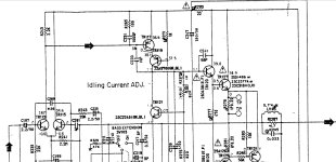
Yes, a problem around TR127 could be responsible for lack of bias current and crossover distortion.
The TR121 collector to emitter voltage (i.e. voltage between the bases of TR123 and TR125) should be a bit more than 2.2V
For quick perspective, would you measure the voltage at the output, at base TR123 and base ofTR125?
The TR121 collector to emitter voltage (i.e. voltage between the bases of TR123 and TR125) should be a bit more than 2.2V
For quick perspective, would you measure the voltage at the output, at base TR123 and base ofTR125?
Last edited:
Thank you BSST for your respond 🙂
This is what my multimeter says:
TR121: C-E = 0.43V
TR123: Ground-B = 1.19V
TR125: Ground-B = 0.75V
This is what my multimeter says:
TR121: C-E = 0.43V
TR123: Ground-B = 1.19V
TR125: Ground-B = 0.75V
I also replaced both output transistors, but still distortion, very weak crackling left channel and no bias.
At the headphones both channels sound good.
At the headphones both channels sound good.
TR123: Ground to B = 1.17V
TR127: Ground to B = 0.61V
TR129: Ground to B = 0.61V
TR125: Ground to B = 0.73V
I did not exactly understand measurement points, so i also measured:
TR123 -B to TR127 -B = 0.55V
TR125 -B to TR129 -B = 0.12V
(The final output transistors are TR127 + TR129)
TR127: Ground to B = 0.61V
TR129: Ground to B = 0.61V
TR125: Ground to B = 0.73V
I did not exactly understand measurement points, so i also measured:
TR123 -B to TR127 -B = 0.55V
TR125 -B to TR129 -B = 0.12V
(The final output transistors are TR127 + TR129)
By "Output" I was trying to refer to junction of R279 and R281. I'm sorry for the ambiguity. And for clarity/brevity, I recommend using black voltmeter tied to ground and reporting any negative voltages as negative numbers.
So if I interpret correctly, the base of TR129 and TR129 are identical at +0.61V Base-emitter voltage of TR125 is only 0.12V? And is TR125 base more positive than its emitter?
The schematic depicts R325 as a 2.2 Ohm resistor from output to ground. Is this correct? Can you confirm with an Ohmmeter? This astounds me!
Thank you for your help. What you summarize matches.
At the junction where R279 and R281 are serial connected i read: -0.005V to -0.010V
Base of TR127 and TR129 are identical: 0.61V
B-E voltage TR125 indeed: 0.12V / B= 0.75V E=0.61V (Base more positive)
R325 (and i guess 326 also) : 2.4 Ohm.
I replaced TR 121/123/125 for 2sc1845/2sc2383/2sa1013. The receiver is acting exactly the same after replacement: No bias reading (R279), poor sound / a quiet crackle distortion at left channel.
I can't imagine why the designers would tie a 2.2 Ohm resistor across the amp output! Part of a Zobel network, sure--- but full spectrum?!
MEMBERS, any ideas?
Ingy76, what is wattage on this resistor? Any sign it's been hot? Would you measure voltage across R267?
MEMBERS, any ideas?
Ingy76, what is wattage on this resistor? Any sign it's been hot? Would you measure voltage across R267?
..........i guess it should be a zobel nw. (2,2 ohm 0,033uf),
a connection could be drawn wrong................
a connection could be drawn wrong................
@Ingy76
As a final sanity check that I haven't overlooked something, would you make a couple of unpowered resistance checks: resistance from left-channel ground binding post to bottom side of R325 and to the Test Point at the junction of R279 and R281?
The request for voltage across R267 probably looked off topic. I'm looking for confirmation that reasonable current is being delivered to the bias network--- i.e. a reason for missing bias current in outputs other than failed power/driver transistors.
R325 looks good, it's unscorched / undamaged.
Across R267 it gives: 0.764V (0.012V [R267] 0.745V at the sides to ground)
Across R267 it gives: 0.764V (0.012V [R267] 0.745V at the sides to ground)
This amp does give a headache. Main circuit board diagram is very poor quality. Really a puzzle to find components. 😆
And only the transistors numbers are marked / written on the board.
And only the transistors numbers are marked / written on the board.
Left-channel ground binding post to the Test Point at the junction of R279 and R281: Rising from 10k to more than 20k Ohm.@Ingy76
As a final sanity check that I haven't overlooked something, would you make a couple of unpowered resistance checks: resistance from left-channel ground binding post to bottom side of R325 and to the Test Point at the junction of R279 and R281?
The request for voltage across R267 probably looked off topic. I'm looking for confirmation that reasonable current is being delivered to the bias network--- i.e. a reason for missing bias current in outputs other than failed power/driver transistors.
Left-channel ground binding post to bottom side of R325: similar as above. Same rising....
As a test yesterday evening, i sprayed some freeze spray around TR113 R265 TR115 R241 and then the bias voltage shot up considerably at left channel, causing the relay to close. Does that give an indication.... or am I looking in the wrong area?
But R265 and 241 values are good. TR's are replaced.
But R265 and 241 values are good. TR's are replaced.
Freeze spray had no effect this night. Tested many components.
It's really a mystery to me. Right channel bias can be adjusted well and works fine. The left just stays at 0.001mv.....
It's really a mystery to me. Right channel bias can be adjusted well and works fine. The left just stays at 0.001mv.....
Your freeze spray probably did exercise the problem. Tough to localize the defect though since spray tends to be broad. My favored approach is to probe for symptoms that don't make sense while the circuit is misbehaving.
Of course, work comes first! We work to support our hobbies, right? 😉
I was expecting continuity from binding post to bottom side R325. I thought lower side of R325 was ground and had a direct path to speaker biding post. You might try the same experiment on the Right channel for comparison. I'll study schematic yet again.Left-channel ground binding post to the Test Point at the junction of R279 and R281: Rising from 10k to more than 20k Ohm.
Left-channel ground binding post to bottom side of R325: similar as above. Same rising....
These readings seem suspect. R267 and R269 are both 5.6k so they should split the voltage between output (roughly 0V) and B- rail (-39V ??) so junction between R267 and R269 should be around -20V. Please report readings both sides of these resistors if you don't discover an issue while measuring. Try measuring directly on resistor leads if appropriate--- sometimes a broken board trace is the culprit.R325 looks good, it's unscorched / undamaged.
Across R267 it gives: 0.764V (0.012V [R267] 0.745V at the sides to ground)
Of course, work comes first! We work to support our hobbies, right? 😉

- Home
- Amplifiers
- Solid State
- Yamaha R-3 No Bias L-channel