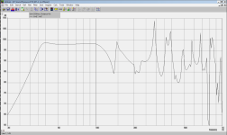
Here's a sim I made of Bose's new tapped horns
documentation is here: https://audioxpress.com/article/patent-review-bose-transmission-line-loudspeaker

US patent is here: https://patents.google.com/patent/US20150071473A1
documentation is here: https://audioxpress.com/article/patent-review-bose-transmission-line-loudspeaker
US patent is here: https://patents.google.com/patent/US20150071473A1
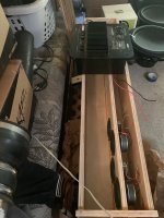
Attachments
![2023-03-30 12_31_13-Xara Photo & Graphic Designer - [Untitled23 _].png](/community/data/attachments/1067/1067269-d72f9b0b48ec7511c5d5299d925d1e92.jpg?hash=1y-bC0jsdR)

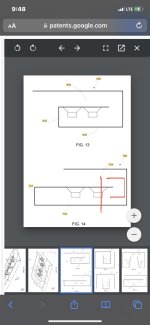
The Akabak model is quite a headache. As far as I can see, this thing can't be simmed with anything but Akabak (Hornresp can't sim it.)
The numbers in the pic above show the various segments. For instance, there's a waveguide segment between "8" and "9" and the throat of the waveguide is defined by the throat area at 8 and the mouth area at 9.
One thing that's "semi-unique" is that the stubs that are intersecting with the horns are made using a "duct" not a "waveguide." Basically, Akabak gets tricky when you have waveguide segments that are reversed. IE, if you have a segment that goes from a large area to a small area, like in a transmission line, you have to mount the waveguide segments backwards in the Akabak simulation. This is because Akabak "waveguides" only get bigger, not smaller. So if you need them to get smaller, you have to mount the segments backwards.
I opted for a duct instead, for the "stubs" in the Bose Tapped Horn. "Ducts" in Akabak don't care if they're mounted normally or backwards, it's all the same.
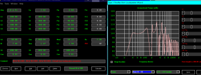
Here's the Akabak model I made. This particular subwoofer uses four of the tried and true MCM 55-1870 woofers.
|DATA EXPORTED FROM HORNRESP - RESONANCES NOT MASKED
|COMMENT: MCM 55-3870 TH
|~~~~~~~~~~~~~~~~~~~~~~~~~~~~~~~~~~~~~~~~~~~~~~~~~~~~~~~~~~~~~~~~~~~~~~~~~~~~~~~~~~~~~~~~~~~~~~~~~~~~~~~~
|REQUIRED AKABAK SETTINGS:
|File > Preferences > Physical system constants:
|Sound velocity c = 344m/s
|Medium density rho = 1.205kg/m3
|Sum > Acoustic power:
|Frequency range = 10Hz to 20kHz
|Points = 533
|Input voltage = 2.83V rms
|Integration = 2Pi-sr
|Integration steps = 1 degree ... 1 degree
|Integration method = Cross
|~~~~~~~~~~~~~~~~~~~~~~~~~~~~~~~~~~~~~~~~~~~~~~~~~~~~~~~~~~~~~~~~~~~~~~~~~~~~~~~~~~~~~~~~~~~~~~~~~~~~~~~~
Def_Const |Hornresp Input Parameter Values
{
|Length, area and volume values converted to metres, square metres and cubic metres:
S1 = 115.20e-4; |Horn segment 1 throat area (sq m)
S2 = 129.60e-4; |Horn segment 1 mouth area and horn segment 2 throat area (sq m)
S3 = 144.00e-4; |Horn segment 2 mouth area and horn segment 3 throat area (sq m)
S4 = 160.00e-4; |Horn segment 3 mouth area and horn segment 4 throat area (sq m)
S5 = 240.00e-4; |Horn segment 4 mouth area and horn segment 5 throat area (sq m)
S6 = 260.00e-4; |Horn segment 5 mouth area and horn segment 6 throat area (sq m)
S7 = 280.00e-4; |Horn segment 6 mouth area (sq m)
D1 = 15.00e-2; | one half of the length of Duct 1
D2 = 22.50e-2; | one half of the length of Duct 2
D3 = 30.00e-2; | one half of the length of Duct 3
D4 = 22.50e-2; | one half of the length of Duct 4
D5 = 22.50e-2; | one half of the length of Duct 5
L12 = 30.00e-2; |Horn segment 1 axial length (m)
L23 = 25.00e-2; |Horn segment 2 axial length (m)
L34 = 20.00e-2; |Horn segment 3 axial length (m)
L45 = 70.00e-2; |Horn segment 4 axial length (m)
L56 = 20.00e-2; |Horn segment 5 axial length (m)
L67 = 24.00e-2; |Horn segment 6 axial length (m)
|Parameter Conversions:
Sd = 71.00e-4; |Diaphragm area (sq m)
}
|~~~~~~~~~~~~~~~~~~~~~~~~~~~~~~~~~~~~~~~~~~~~~~~~~~~~~~~~~~~~~~~~~~~~~~~~~~~~~~~~~~~~~~~~~~~~~~~~~~~~~~~~
|Network node numbers for this tapped horn system:
| 0-Voltage-1
| |
| -Driver-------------
| | |
|8-Segment-9-Segment-10-Segment-11-Segment-12-Radiator
|~~~~~~~~~~~~~~~~~~~~~~~~~~~~~~~~~~~~~~~~~~~~~~~~~~~~~~~~~~~~~~~~~~~~~~~~~~~~~~~~~~~~~~~~~~~~~~~~~~~~~~~~
Def_Driver 'MCM_55-1870'
Sd=71.00cm2
Bl=5.92Tm
Cms=6.76E-04m/N
Rms=1.50Ns/m
fs=64.40Hz |Mmd = 8.69g not recognised by AkAbak, fs calculated and used instead
Le=0.50mH
Re=7.20ohm
ExpoLe=1
System 'System'
Driver Def='MCM_55-1870''Driver1'
Node=1=0=9=20
Driver Def='MCM_55-1870''Driver2'
Node=1=0=11=20
Driver Def='MCM_55-1870''Driver3'
Node=1=0=11=17
Driver Def='MCM_55-1870''Driver4'
Node=1=0=14=17
Waveguide 'Horn segment 1'
Node=8=9
STh={S1}
SMo={S2}
Len={L12}
Conical
Waveguide 'Horn segment 2'
Node=9=10
STh={S2}
SMo={S3}
Len={L23}
Conical
Duct 'Duct segment 1'
Node=10=11
SD={S3}
Len={D1}
Duct 'Duct segment 2'
Node=11=12
SD={S3}
Len={D1}
Waveguide 'Horn segment 3'
Node=10=13
STh={S3}
SMo={S4}
Len={L34}
Conical
Duct 'Duct segment 3'
Node=13=14
SD={S4}
Len={D2}
Duct 'Duct segment 4'
Node=14=15
SD={S4}
Len={D2}
Waveguide 'Horn segment 4'
Node=13=16
STh={S4}
SMo={S5}
Len={L45}
Conical
Duct 'Duct segment 5'
Node=16=17
SD={S5}
Len={D3}
Duct 'Duct segment 6'
Node=17=18
SD={S5}
Len={D3}
Waveguide 'Horn segment 5'
Node=16=19
STh={S5}
SMo={S6}
Len={L56}
Conical
Duct 'Duct segment 7'
Node=19=20
SD={S6}
Len={D4}
Duct 'Duct segment 8'
Node=20=21
SD={S6}
Len={D4}
Waveguide 'Horn segment 6'
Node=19=22
STh={S6}
SMo={S7}
Len={L67}
Conical
Radiator 'Horn mouth'
Node=22
SD={S7}
Like many of the Bose subwoofer designs, it squeezes a lot of bass out of relatively small woofers. In this case, I'm using four MCM 55-1870 woofers, which would normally be struggling to play 80Hz. By putting those five inch woofers in this Bose Tapped Horn, they end up playing down to 35Hz, much lower than you'd expect from such small woofers.
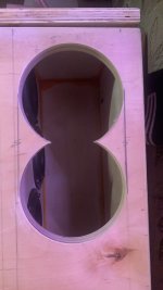
Attachments

Yeah I'm curious how it would perform with some cheap eights instead of cheap fives
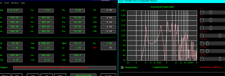
The short acoustical circuits mess with my mind . If I sim those individually (tighter and tighter) they create more and more ‘spike’ at resonance instead of when spread out. What do you guys think ?
Attachments
Last edited:
There are easier ways to achieve the same bandwidth with less out of band noise artifacts. I wonder what specific purpose Bose has in mind for this type of design?
Like most Bose designs, it maximizes the low frequency corner at the cost of space.
If you look at the Bose "triple reflex" designs, there's nearly nothing that will get you a lower F3 for a given set of driver parameters:
https://www.diyaudio.com/community/threads/post-your-triple-reflex-bandpass-designs.186855/
Bose abandoned their Triple Reflex subs quite a while back. If I had to speculate, my bet is because the Triple Reflex alignment is VERY unforgiving of parameter creep. Basically, if your QTS goes up with age (which it will) the box is tuned all wrong.
Transmission lines are way more forgiving, because all the segments are connected.
So I'm betting that this Bose Tapped Horn is optimized for:
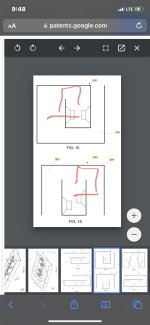
1) very low profile. Note that it's low profile enough to fit inside of a television. I have a Samsung 85" TV, and it's so big, you get honest-to-God bass and imaging from the TV, due to the fact it's quite huge.
2) These Bose Tapped Horns play low. A 35Hz F3 for a cheap 5" woofer is no joke.
3) Efficiency can be fairly high if you have space for a big box.
I'd argue that if you have space for a high excursion conventional woofer in a conventional box, it's probably less hassle. But if you need a very low profile, the Bose Tapped Horn is interesting.
If you look at the Bose "triple reflex" designs, there's nearly nothing that will get you a lower F3 for a given set of driver parameters:
https://www.diyaudio.com/community/threads/post-your-triple-reflex-bandpass-designs.186855/
Bose abandoned their Triple Reflex subs quite a while back. If I had to speculate, my bet is because the Triple Reflex alignment is VERY unforgiving of parameter creep. Basically, if your QTS goes up with age (which it will) the box is tuned all wrong.
Transmission lines are way more forgiving, because all the segments are connected.
So I'm betting that this Bose Tapped Horn is optimized for:
1) very low profile. Note that it's low profile enough to fit inside of a television. I have a Samsung 85" TV, and it's so big, you get honest-to-God bass and imaging from the TV, due to the fact it's quite huge.
2) These Bose Tapped Horns play low. A 35Hz F3 for a cheap 5" woofer is no joke.
3) Efficiency can be fairly high if you have space for a big box.
I'd argue that if you have space for a high excursion conventional woofer in a conventional box, it's probably less hassle. But if you need a very low profile, the Bose Tapped Horn is interesting.
What’s the sim look like as an enclosure(can you sketch it ?) ?
I wanna build this with tangband w5 (x4). I’ll just find the correct CSAs in HR and make some assumptions based on your akabak model.
I wanna build this with tangband w5 (x4). I’ll just find the correct CSAs in HR and make some assumptions based on your akabak model.
- Home
- Loudspeakers
- Subwoofers
- Bose Tapped Horn