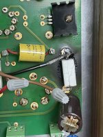
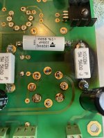
I built my 2nd SSE maybe 5 or 6 years ago. Been working fine with no issues until about 2 months ago, when it started randomly blowing the fuse every few weeks or so, playing fine in between. Then about a week ago I started hearing static, almost like a grounding issue, in the right channel. Checking the input connection and replacing tubes didn’t fix the issue. I then remembered on my 1st SSE a wire on a board connector to the PC loosened up causing a problem with one channel, so I took a look to see if that was the issue on this one. What I found was in the right channel R17 (560-ohm 5W) was fried and C15 (1500uf 50V cap) didn’t look very good either. I’m surprised the channel was working at all. The same components on the left channel look fine. I have the parts to replace them, but I’m wondering if I should chalk it up to part failure, or should I be looking at what else may have caused those parts to fry? The U10 CCS screw that holds it to the board was bright silver when new but looks dull now. Maybe from heating up? The U20 CCS screw looks like new, bright. Could the CCS have caused the problem? Should I replace the U10 CCS also? I do have some extra IXCP10M45S on hand. Picked a few when Digi Key still had them awhile back. What other part(s) could have caused R17 and C12 to fry? Since it was playing well up until I looked underneath, (I even had it cranked up last Friday night and it sounded good, without static!), so I suppose I could replace the parts and then take some voltage readings to see if anything looks odd and figure that out then. Any help or thoughts would be appreciated, thanks, Mike.
Attachments
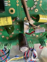
Quick update. After removing the PC board from the cabinet and further examining it, the left channel seems to be having the same issue as the right. Resistor R27 has a slight crack in it and cap C22 is starting to bulge on top. Both are nowhere near as bad as R17 and C12, but appear to heading in that direction. Hmm, so something is messing with both channels, but one side worse than the other? Thanks for any additional insight, Mike.
Attachments
Sunil,
I’ll admit I haven’t taken any recent measurements, but I have notes when I last measured a few years back.
Output tube: Tung-Sol 6550
B+: 417V
R17: 470 ohm (560 ohm + 3k in parallel)
Plate voltage: 396V
Cathode voltage: 38V
So, this should give a cathode current of 80mA and about 28W dissipation I believe. Maybe pushing the tube to 70%. Not real overly aggressive. But, as I said, I haven’t been monitoring the measurements for 2, maybe 3 years. And the tube is 3 years old, and used for hours every day, sooooo? I guess I should have kept monitoring values in the tubes old age. Interestingly, it’s sounded very good. After looking at the board I’m surprised it sounded so good. The right channel tube never appeared to be glowing red or more so than the left channel. But maybe I just didn’t notice. Thanks.
You may have gassy tubes that go into a red plate runaway condition after being powered up for some time. That is the likely cause of excess cathode voltage. A leaky coupling cap can do it too but it usually causes distortion bad enough to be noticed.
Thanks George. I think I'll try and clean up the board a bit and then replace both coupling caps along with both cathode resistors and bypass caps along with some newer tubes. I have the parts on hand. If I can get this back up and running again, I'll keep an eye on the voltage readings. Thanks again.
The voltage numbers look about right. I'm not running anywhere near 80ma. My 6BG6GA are running with 410v /32v and ~ 60ma (560R). I use 7W Welwyn resistors. EL34s and 6L6WGB were about the same, give or take 1-2v.
I wonder why the caps are farting out. G.A obviously has more experience and his point about gassy tubes could be the reason you're having problems.
Does monitoring the cathode voltage help identify a tube that is going crazy ?
I wonder why the caps are farting out. G.A obviously has more experience and his point about gassy tubes could be the reason you're having problems.
Does monitoring the cathode voltage help identify a tube that is going crazy ?
When a tube runs away it will draw an ever increasing amount of current. In doing so the voltage across the cathode resistors rises. Eventually it rises beyond the voltage rating of the bypass capacitors causing them to become leaky and eventually short out. The shorted cap will remove all bias causing the current in the output tubes to skyrocket. In extreme cases the resistor will fail to an open circuit forcing the current through the leaky cap causing it to vent or explode.
The board picture in your other thread indicates that those resistors got REALLY HOT, so something caused a lot of current flow through them.
Most vacuum tubes made years ago had a very good vacuum and rather pure materials for the internal elements. Some new production stuff isn't quite as good. They work fine for a while, but impurities trapped inside the metals and insulators get released by heating cycles. These impurities can ionize creating "gas" inside the tube which causes grid current and increased cathode current, producing more heat which perpetuates the cycle until the tube current can't be controlled and a runaway condition occurs. Yes, watching the cathode voltage, or checking it periodically once the amp has been on for an hour or so is a good idea. A cathode current that slowly creeps upward over time is not a good sign.
Older tubes usually just slowly lost emission as their cathodes wore out. Many new production power output tubes fail by runaway, which unfortunately causes collateral damage.
Your board may still be usable if the resistance across the resistor connections reads open with no resistor or cap in place. Always mount the resistors so there is some space between them and the board to allow air flow. The larger the resistor, the greater the space. I usually space the white 5 and 10 watt parts at least 1/4 inch above the board.

Thanks, George, for your in-depth explanation. The Tung-Sol 6550’s I was using are several (3-4) years old and were used a lot. I didn’t push them too hard as the PT is an Allied 6K7VG with a (somewhat?) recommended 150mA limit. With a B+ of about 415V I ran it on a switchable bias resistor of either 440, 470 or 571, with Vk of either 35V, 38V or 39V which ended up with a total of 186mA, 180mA or 158mA with the 12AT7 included. They were never pushed beyond that. So, after your explanation I’m thinking it was one of the tubes entering end of life. Well, maybe both, as the left channel R27 and C22 showed signs that they were heading in the same direction. What’s really even worse than frying those parts, is that it was all easily avoidable, as I have test points on the top plate wired across both cathode resistors! At anytime I could have taken resistance (powered off) and voltage (powered on) readings to evaluated what was happening and taken action before it went this far, sheesh. To Jcris, that’s why the wire nuts are there for the test point connections. A lesson well learned, for sure!
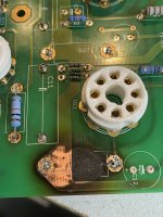
So, I did clean up the board. Resistance reading across R17 connections does read open. I replaced (on both right and left channels), the coupling cap (in case of leakage), cathode resistor (raised up ¼”) and bypass cap. I may have to adjust the bias as previously I had a base resistor of 680 ohm, but only have 560 ohms on hand. I have a switch to change the bias, but that won’t work with the 560, so I may just leave it without the switch. With a B+ of about 415 I’ll maybe get 73Ik on a 6550 and around 162mA total with the 12AT7, and that should help to keep the tubes and PT happy. That bias should also work for 6L6GC’s, which I’ll use for testing until I pick up some new 6550’s, which I prefer. I have some cheap Chinese 6L6GC’s that Antique Electronics were selling a number of years ago. Supposedly indestructible. But I believe I read George found a way to take at least one out!
Thanks again George for your insight.
Attachments
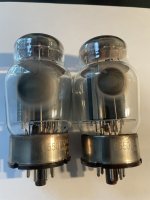
The nearly exhausted getter spot on those 6550's says GASSY! When they start to look like that runaway is likely.
My old SSE had a pair of EH 6550's in it and I ran it at around 100 mA per tube (not recommended) and everything got HOT. The poor Allied 6K7VG ran too hot to touch after being on for 30 minutes or so. The amp was used for powering my PC's speakers so it was on whenever the computer was on. Oddly enough that amp remained stable for about 3 years until it was replaced by a push pull amp. Unfortunately it got dropped when I moved everything out of Florida 8 years ago. It's a bit bent up and ugly, but it still works!
My old SSE had a pair of EH 6550's in it and I ran it at around 100 mA per tube (not recommended) and everything got HOT. The poor Allied 6K7VG ran too hot to touch after being on for 30 minutes or so. The amp was used for powering my PC's speakers so it was on whenever the computer was on. Oddly enough that amp remained stable for about 3 years until it was replaced by a push pull amp. Unfortunately it got dropped when I moved everything out of Florida 8 years ago. It's a bit bent up and ugly, but it still works!
You are spot on George! I think I tried to use the Tung-Sol 6500’s far too long (because of new prices) without monitoring the health of them as I should have. I was fooled by the sound being so good, while unknowingly some parts of the amp were disintegrating without my hearing it. Maybe as tubes degrade slowly, we don’t notice it until it’s too late (for me anyways)? I think it’s a tribute to you that that this amp, designed by you, withstood whatever huge abuse I inflicted upon it, and was able to rebound with just a few component changes.
I have completed my fixes, and all is well. Playing as before the meltdown! Using cheap 6L6GC for now to test, and all is well!
Thanks again George. I appreciate you, your work, and help.
I have completed my fixes, and all is well. Playing as before the meltdown! Using cheap 6L6GC for now to test, and all is well!
Thanks again George. I appreciate you, your work, and help.
Attachments
- Home
- More Vendors...
- Tubelab
- SSE Trouble