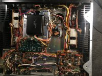
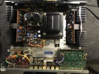
Grounding issues are a pain, and trying to sort out a unit someone else has messed with is a pain. Here I have both issues in one.
Someone had messed with ground wiring at the input terminals. I think I sort of got it how it should be but am still having a weird issue. I've done a recap/overhaul on the unit but am stuck on this grounding issue.
Currently, there is a buzz in both channels.
Originally if I had a signal connected to tuner or aux it would bleed through when unselected. Distorted and at normal listening levels, unaffected by volume. The ground wire from the input switching board had been grounded to the ground of the input jacks. When I put it on the chassis this stopped happening. But there is still a buzz in the output. Unaffected by volume as well. And it is coming from the preamp as it is gone when I run a signal directly into the amp. It did seem to make some difference to the noise where I grounded this wire. If I grounded it to the ground bus at the main caps, it was louder than when grounded to the smaller bus near the terminals.
Here's the weird part that I'm hoping will give enough of a clue to figure this out.
If I ground the input signal to anywhere on the chassis, I get that distorted bleed through again. That definitely isn't normal.
I'm pretty sure this issue was here before I did my work, but someone was in here before.
Any ideas?
Attachments
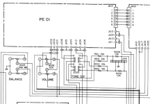
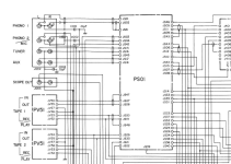
First, a curiosity, probably not relevant: pot R009 feeds pot R010. I believe R010 is the main volume control. Where is the R009 physical location and what is its function?
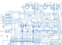
I suggest continuing experiments with that grounding wire; use a relatively heavy gage wire as short as experimentation permits and be alert to how the wire is routed; it might be susceptible to magnetic fields from the transformer. While the grounding wire is disconnected, determine how/where the ground connection depicted in the schematic near C10 in the power supply is implemented; having the ground floating might aid ohmmeter exploration. I'm not suggesting any change--- just think it might lend insight to restoring the original implementation. Look for evidence that your predecessor might have added ill-advised ground connections.
I like your experiments about finding a good point for ground wire connection, but it's not always obvious what's a good connection point. Note that large 120Hz currents flow in the C10 capacitors, so connecting at point E near the common junction of the C10 caps may not be optimum. Connection near speaker common might be interesting.
Keep us posted. Good luck!
I believe that grounding of the input board is suspect since you've described its involvement in the problem and you note that volume control position has no effect.Grounding issues are a pain, and trying to sort out a unit someone else has messed with is a pain. Here I have both issues in one.
Someone had messed with ground wiring at the input terminals. I think I sort of got it how it should be but am still having a weird issue. I've done a recap/overhaul on the unit but am stuck on this grounding issue.
Currently, there is a buzz in both channels.
Originally if I had a signal connected to tuner or aux it would bleed through when unselected. Distorted and at normal listening levels, unaffected by volume. The ground wire from the input switching board had been grounded to the ground of the input jacks. When I put it on the chassis this stopped happening. But there is still a buzz in the output. Unaffected by volume as well. And it is coming from the preamp as it is gone when I run a signal directly into the amp. It did seem to make some difference to the noise where I grounded this wire. If I grounded it to the ground bus at the main caps, it was louder than when grounded to the smaller bus near the terminals.
Here's the weird part that I'm hoping will give enough of a clue to figure this out.
If I ground the input signal to anywhere on the chassis, I get that distorted bleed through again. That definitely isn't normal.
I'm pretty sure this issue was here before I did my work, but someone was in here before.
Any ideas?
I suggest continuing experiments with that grounding wire; use a relatively heavy gage wire as short as experimentation permits and be alert to how the wire is routed; it might be susceptible to magnetic fields from the transformer. While the grounding wire is disconnected, determine how/where the ground connection depicted in the schematic near C10 in the power supply is implemented; having the ground floating might aid ohmmeter exploration. I'm not suggesting any change--- just think it might lend insight to restoring the original implementation. Look for evidence that your predecessor might have added ill-advised ground connections.
I like your experiments about finding a good point for ground wire connection, but it's not always obvious what's a good connection point. Note that large 120Hz currents flow in the C10 capacitors, so connecting at point E near the common junction of the C10 caps may not be optimum. Connection near speaker common might be interesting.
Keep us posted. Good luck!
@BSST R009 appears to be connected to the tone bypass switch. It is on a terminal strip mounted to the inside of the front of the chassis near the volume control.
I'm not sure what experiments to try with the ground wire because I did play around with it, but I can play around a bit more.
Does it give any good clues that I can put the signal to the output through the ground? When I ground the signal to the ground at the input it comes through distorted at normal listening levels, unaffected by volume control location.
Attachments
Hi Racoon,
Interesting that we seem to be viewing different schematics. I attempted to upload the manual, but apparently it's too large (28.2 MB) for the server. I found a low resolution option that I could upload. My original source was https://www.manualslib.com/ where the resolution was good. On page 44, right side I found main volume control R010 which features a loudness tap. On page 45 near center, I found R009.
Where did you ultimately connect the ground lead from the input board? Does the amp in fact have a 3-wire ground cord and does its ground pin have continuity to the chassis?
Yes, this seems interesting. Would you provide more detail? You are touching center signal pin of an RCA cable to chassis? Is the source a separate equipment with no direct connection of grounds between them? If you make an resistance measurement between between the amp's chassis and the selected source, what do you find?Does it give any good clues that I can put the signal to the output through the ground? When I ground the signal to the ground at the input it comes through distorted at normal listening levels, unaffected by volume control location.
Attachments
Add a series 1k to each audio input that bleeds through, before the following switch.
Then when that input is deselected and grounded, it will not bleed through.
Then when that input is deselected and grounded, it will not bleed through.
That might solve the bleedthrough, but the bleedthrough and the buzz must be related.
I should be able to fix this without modifying the original design. If I fix it by modifying the design, I'll just be compensating for the underlying issue without fixing it.
I should be able to fix this without modifying the original design. If I fix it by modifying the design, I'll just be compensating for the underlying issue without fixing it.
They could be, but the odds are they are not related.
It is very poor practice to just short out a source without an intervening impedance.
It is very poor practice to just short out a source without an intervening impedance.
I used the schematic from hifiengine. This is the D (dolby) version of this model. That may or may not be relevant.Hi Raccoon,
Interesting that we seem to be viewing different schematics. I attempted to upload the manual, but apparently it's too large (28.2 MB) for the server. I found a low resolution option that I could upload. My original source was https://www.manualslib.com/ where the resolution was good. On page 44, right side I found main volume control R010 which features a loudness tap. On page 45 near center, I found R009.
Where did you ultimately connect the ground lead from the input board? Does the amp in fact have a 3-wire ground cord and does its ground pin have continuity to the chassis?
Yes, this seems interesting. Would you provide more detail? You are touching center signal pin of an RCA cable to chassis? Is the source a separate equipment with no direct connection of grounds between them? If you make an resistance measurement between between the amp's chassis and the selected source, what do you find?
I grounded the wire from the input board to a point near the input terminals. The wire was about the right length for that, so it must be supposed to go there somewhere.
Interestingly the ground configuration of the input jacks are a bit different between the two schematics.
This unit just has a two prong cord. I did try running a ground wire to wall ground but it made no difference.
I'm using an ipad as a source. Same way I test most things when they are on the bench.
Yes I was jumping the center pin of the signal to the chassis. But when the input I'm using is deselected, jumping either the negative or the positive of the input jack to ground does it since the switch shorts them together.
Attachments
I managed to figure this out. The buzz and bleedthrough issues were indeed unrelated. A broken ground on the volume pot was responsible for the buzz. I'd have found it right away if I'd had an identical unit on the bench beside it.
- Home
- Amplifiers
- Solid State
- Marantz 1150D Integrated Amp Grounding Issue