Can anyone explain me why there is no capacitor between C & B of Q5 just like Q6? I purchased a pair of pcb but before populating it i made a veroboard version for experimentation & i have this question in my mind.


Nice work as first buildCan anyone explain me why there is no capacitor between C & B of Q5 just like Q6? I purchased a pair of pcb but before populating it i made a veroboard version for experimentation & i have this question in my mind.
View attachment 1156517
View attachment 1156519
The C6 cap on Q6 prevents stability issues with CFP output stages. The cap is only needed on the negative side and most designed that I've read state that the cause for this is entirely not understood. I believe it's mentioned somewhere on the ESP site in the articles section, but I can't seem to locate it. I've also read that on the P3A this oscillation normally doesn't occur. It's there to address the infrequent times when it does occur.
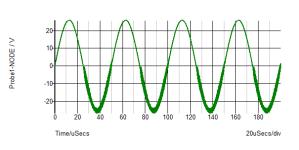
Yes, the additional phase shift in the complementary output pair can cause oscillations. Here is a simulation of a classic circuit similar to the one nF posted without the Miller capacitor. You can see the PNP/NPN pair has given rise to a fuzzy output.
In simulation I don't see the need for C6 when the Miller is included but it was a common feature of older classic designs as a precaution. I have certainly seen the additional capacitor to be necessary in some of the constructions I have built, though. Simulations aren't everything, but layout often is the difference between reality and sim.
In simulation I don't see the need for C6 when the Miller is included but it was a common feature of older classic designs as a precaution. I have certainly seen the additional capacitor to be necessary in some of the constructions I have built, though. Simulations aren't everything, but layout often is the difference between reality and sim.
Attachments
I've noticed many P3a builds have oscillation problems. You notice the designer suggested older MJL21193/4 and 15032/33"s.
Much lower Ft (and Hfe) in those older devices , The positive feedback in the CFP OP stage is less critical and can be "swamped out" by the main pole
in the VAS. CFP current gain is close to an EF3 @ 50-100K gain. Ripple at the main OP is fed back to the driver. I can't understand why the P3a is so popular
versus a good stable triple OPS. CFP adds 2 more nested positive feedback loops to the amp as a whole.
I'll have to simulate a P3A type input stage driving an EF3 , bet I can get 10-20 ppm @ 20K if I tweak it. Plus WAY more stability.
I’ve never considered The P3A as a low distortion amp. I feel it follows the FirstWatt approach of sounding good through simplicity rather than measuring well.
Also, I’ve tinkered with the design quite a bit in simulation. In simulation, adding 10R of degeneration to the drivers helps quite a bit to tame the CFP output.
I also find that adding a current compensation resistor to the bias generator helps quite a bit with thermal stability.
Change any more and starts to mess with the character of the design.
Yes, i have read that if you try to upgrade P3A everything becomes worse. If you remember rod used a speed up capacitor (2.2uf if i can recall correctly) across the VBE multiplier (Q9) but in new updated version he omitted it. I don't know why he did that because many popular design includes it & with my limited knowledge i see no harm using that capacitor.
Anyway i'll follow rods recommendations except VAS stage, where i'm going to use much faster KSA1381. For output & driver TR i have TIP35/36c, MJL21193/94, ST BD139/40.
Anyway i'll follow rods recommendations except VAS stage, where i'm going to use much faster KSA1381. For output & driver TR i have TIP35/36c, MJL21193/94, ST BD139/40.
Last edited:
Actually i heard that modern bd139/40 pair isn't as good as older philips part & not recommended for voltage amplification stage. So i want to use those as driver transistor for which they are still very popular & yes ksa1381 has lower COB.
You might already be aware... but just in case, Sakis (user east electronics) is one the top P3A authorities on this forum. Here has two long threads that discuss parts selection. The use of BD140 vs KSA1381 is discussed. It supports what you have described.
P3A Comparison table ( long .... )
P3A-More upgrades
P3A Comparison table ( long .... )
P3A-More upgrades
Why not ditch the P3A , build something more "bulletproof". This is Like some of the old kits of the 70's , where everyone was fighting with
oscillations and layout considerations.
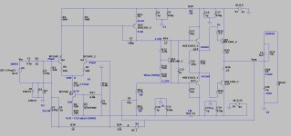
Here is something - guaranteed. even with garbage parts would be a more solid project. Just add a current mirror to the LTP , and it IS a
"audiophile amp".
OS
PS - MJE340 , BDxxx , or KSA (Cob) does not matter for a low bandwidth amp like this !!! 200-300K unity gain BW.
oscillations and layout considerations.
Here is something - guaranteed. even with garbage parts would be a more solid project. Just add a current mirror to the LTP , and it IS a
"audiophile amp".
OS
PS - MJE340 , BDxxx , or KSA (Cob) does not matter for a low bandwidth amp like this !!! 200-300K unity gain BW.
Attachments
Last edited:
CFP will usually be unstable and more likely start ringing on the negative rail.
So the usual fix or assumption is to add C6
Even in a good simulation model, C6 will reduce ringing further, but still be there.
With normal music or " program material" it is usually " good enough"
to be stable.
Otherwise using square wave at higher frequencies
C6 reduces ringing but wont fix the problem.
I like my amps to personally be unconditionally stable even with
square wave analysis/testing to at least 20 to 27 k
This case the differential input can be tamed with De Generation resistors.
And fix the problem entirely. The absurd C6 can be removed
and C4 lowered.
Rod loves his boot straps, but the VBE multiplier should have additional
capacitors added for stability with such a crude current source.
On a positive note, I think these designs still give pleasing results
since there is a more dominant 2nd harmonic to the distortion profile.
Majority comes from the slow, low gain Vas / 2nd gain stage.
likewise the slow low gain 2nd gain stage demands to much current
from the differential pair and requires excessive current to work.
Excessive current in the diff pair can appear to reduce distortion or needed
for correct DC offset.
But likewise causes possible instability. Hench easy fix is basic de generation.
180 to 330 ohms likely sufficient
Last edited:
First of all i want to thank everyone for continuing this thread & a special thanks to ostripper for providing me a good design. The thing is in earlier days of my hobby i made various chipamps (i still have a soft corner for those) but in recent years i moved on to discrete amplifiers. I have many projects in pipeline including Circlophone which is very stable & i already bought pcbs for it. So i'm going to experiment with a lot of different amplifier topologies & not going to ditch P3A 😉
Even as a "noobie" , I shied away from things like the P3A and the ESP sub amp because they conflicted with what I read in Self's books.
They are just bad designs. I glad I took this path and now we have Badgers , Slewmasters , and (even Wolverines). It is a shame that with just a
few more components both those ESP projects could be much more "solid". Self even mentions the "folly" of CFP OPS's in his books.
I suppose it would come down to what you want .... an amp that will last decades between re-cappings , or "issues" ??
Hi Pete,
I respect your knowledge and you contributes here are amazing. However, I disagree with you here. Rod Elliotts designs are bad from the perspective of Douglas Self or Bob Cordell, but not universally bad. They simply follow a different design philosophy.
His designs have been around and proven reliable for decades. The P3A in particular is over 50 years old. I’d call that pretty robust.
It is a different approach than the blameless style amp and won’t appeal to everyone. In the same way a blameless amp doesn’t appeal to those that like Nelson Pass’s designs. Based on Douglas Self’s approach, the FirstWatt designs could be labeled as bad too. I wouldn’t agree with this either - they’re just different.
For those interested in the P3a, build it and see if it appeals to you. Maybe it does or maybe you prefer a less colored sound. It’s your money and ears, build whatever you like.
- Home
- Amplifiers
- Solid State
- Q about ESP Project 3A