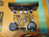
Now that I have more time, I decided to produce this amplifier.
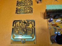
Laid out the P.C.B and made them myself.at home.
I still need to fabricate. a couple of heatsinks for the bridge and the driver transistors.
When I have done this, I will wire everything into a temporary case and test.
Looking forward to this so far it has been very satisfying to return to the audio hobby.
Attachments


Looks neat.
I always do my own pcb designs and get the made by JLCPCB.
Its just a lot less hassle than rolling my own and cheap.
And I end up with pro looking pcb with proper solder mask and silk screen.
Its 40 years since I last made my own pcb using light box etc
I always do my own pcb designs and get the made by JLCPCB.
Its just a lot less hassle than rolling my own and cheap.
And I end up with pro looking pcb with proper solder mask and silk screen.
Its 40 years since I last made my own pcb using light box etc
Hey! Looks great! Let's appreciate the little things. Like colour coordination: PCB matches the workbench!
Joke aside, it looks like a long-tailed pair input with current mirror--would you care to share the schematics (out of curiosity)? Is it a well-known design, or your own?
--Christian
Joke aside, it looks like a long-tailed pair input with current mirror--would you care to share the schematics (out of curiosity)? Is it a well-known design, or your own?
--Christian
Thanks everybody. For your comments.
to answer some of your questions I made these boards for proof of concept only.
once these are fully developed, I will get some professionally. Made.
the design is basically the Self circuit with CFP Outputs and some component changes.
the drivers and VAS are MJE243 253 And the outputs. 5200 1943.
I also have several other designs in the works. including a preamp and phono stage these are in the early stages as yet.
the end results will be compared against my other equipment an Arcam A29 class G and Exposure Intergrated.
These will be driven by Oppo. UPD205 and Arcam CDS 50 into Dynaudio Evoke 30/ Acoustic Energy AE 100/B&W603.
for all comparative tests.
Not sure where all this will end up, but the process should be at least interesting.