This 1965 paper was discussed on the UK Vintage Radio site, but did not get many comments, and I wondered if it would appeal to some of the more technical DIYers here.
It describes a novel solution to create a 'laboratory' amplifier with a distortion limit of 0.1% over an extensive audio range. The solution uses a mixture of feedback from the OPT Primary and Secondary, with a small transformer working with high and low pass filters to solve the problem of a non ideal OPT.


It describes a novel solution to create a 'laboratory' amplifier with a distortion limit of 0.1% over an extensive audio range. The solution uses a mixture of feedback from the OPT Primary and Secondary, with a small transformer working with high and low pass filters to solve the problem of a non ideal OPT.
Attachments

Very Creative.
Probably works very well with the original feedback transformer and the original output transformer.
Any other feedback transformer, and any other output transformer . . .
There are very large variations of non ideal feedback transformers and non ideal output transformers.
Your Mileage May Vary
I am not planning a trip to Las Vegas.
This kind of split FB paths is often found in instrumentation amplifiers, in particular what designers had to do before SS & digital methods.
Well covered in some of the ancient text books. The example circuit given could be simplified a lot to pull out what the author intends.
As a starter, why does the cct need a cascode front end when a single triode would do? And a brute force double pentode phase splitter?
That does fix the LF problem of the ratio of the AC vs DC loadline on the drivers. But as is overkill. The path from the cascode is an LF shelf,
a common fix.
OTOH, building for good LF response is not much of a problem when NFB is used. Getting good response at the top end is a different story.
Pushing the audio thru the OPT Leakage Reactance is like pushing a rope up a hill.😱
Reason for the cascode front end ...

... and the phase splitter is justified here ...


Would be interesting to build a stereo amp with 4 tubes in phase splitter duty instead of a single dual triode.
... and the phase splitter is justified here ...
Would be interesting to build a stereo amp with 4 tubes in phase splitter duty instead of a single dual triode.
First stage noise figure has been compromised by running at quite low plate current
Refer to the Gm vs plate current curves on the E88CC Siemens Data Sheets.
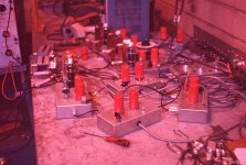
And a link to yet another high gain but low impedance driver, the EFP60 Secondary Emission Pentode.
They have a 9-pin lock-in base. And colored bright red.
https://worldradiohistory.com/Archive-All-Audio/Archive-Audio/50s/Audio-1955-Jun.pdf
During my daze in the research lab we used boxes full of these things to create
pulses with rise times of a few nanoS into 50R transmission line. Magnetic core memory research.
That mess of wire is my test bench. The color slide doesn't look color fast tho. But hey, more than 60 yrs ago.😀
Refer to the Gm vs plate current curves on the E88CC Siemens Data Sheets.
And a link to yet another high gain but low impedance driver, the EFP60 Secondary Emission Pentode.
They have a 9-pin lock-in base. And colored bright red.
https://worldradiohistory.com/Archive-All-Audio/Archive-Audio/50s/Audio-1955-Jun.pdf
During my daze in the research lab we used boxes full of these things to create
pulses with rise times of a few nanoS into 50R transmission line. Magnetic core memory research.
That mess of wire is my test bench. The color slide doesn't look color fast tho. But hey, more than 60 yrs ago.😀