Hello Friends;
My LT3045 and LT3042 Projects are ready for use.
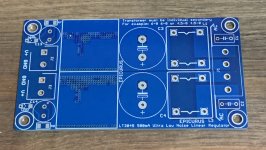
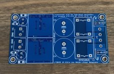
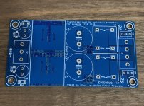
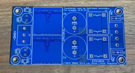
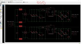
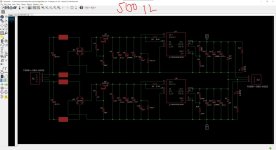
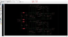
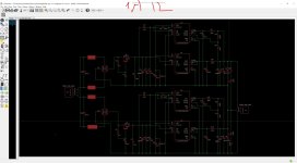
500ma and 1A separate dual dac PSU 3.3V 5V 7V 9V 12V ideal for dac and digital audio
500ma and 1A symetrical PSU +0- 2x9V 2x12V 2x15V ideal for phono amp preamp buffer and dac output stage
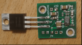
5A 5V LT3045 and transistor desing are for Pi4 and Pi5
Fast starup upgraded
EPIC REG 5V 5A

EPIC REG 5V 5A model output noise for 625mA

EPIC REG 5V 5A model output noise for 2.5A

EPIC REG 5V 5A model output noise for 4A

2 Individual positive regulator with Parallel LT3045 Vout: 3.3V-5V-7V-9V-12V / 1A

2 Individual positive regulator with Parallel LT3045 Vout: 3.3V-5V-7V-9V-12V / 1A
output noise for 3.3V / 150mA <1.204uV

2 Individual positive regulator with Parallel LT3045 Vout: 3.3V-5V-7V-9V-12V / 1A
output noise for 3.3V / 500mA <1.264uV


My LT3045 and LT3042 Projects are ready for use.
500ma and 1A separate dual dac PSU 3.3V 5V 7V 9V 12V ideal for dac and digital audio
500ma and 1A symetrical PSU +0- 2x9V 2x12V 2x15V ideal for phono amp preamp buffer and dac output stage
5A 5V LT3045 and transistor desing are for Pi4 and Pi5
Fast starup upgraded
EPIC REG 5V 5A
EPIC REG 5V 5A model output noise for 625mA
EPIC REG 5V 5A model output noise for 2.5A
EPIC REG 5V 5A model output noise for 4A
2 Individual positive regulator with Parallel LT3045 Vout: 3.3V-5V-7V-9V-12V / 1A
2 Individual positive regulator with Parallel LT3045 Vout: 3.3V-5V-7V-9V-12V / 1A
output noise for 3.3V / 150mA <1.204uV
2 Individual positive regulator with Parallel LT3045 Vout: 3.3V-5V-7V-9V-12V / 1A
output noise for 3.3V / 500mA <1.264uV
Attachments
Last edited:

Can you share the noise level measurement setup, and did you do any spectrum measurements ?
Did you compare performance with alternate diode bridges, such as those with a rated recovery characteristic, and with/without series ac input inductance (which may exacerbate any influence from secondary winding leakage inductance)? Did you not want to locate a local smt bypass capacitor directly at the diode bridge dc terminals?
Did you compare performance with alternate diode bridges, such as those with a rated recovery characteristic, and with/without series ac input inductance (which may exacerbate any influence from secondary winding leakage inductance)? Did you not want to locate a local smt bypass capacitor directly at the diode bridge dc terminals?
I also would be interested about the gerber files. What would be these regulators output mOhms, PSRR?Great job. I was about to design a PCB and have JLPCB build it. Could you please share your schematics or Gerber?
@bohrok2610 You are absolutely right. so I used pgfb resistors in lt3045 4a version. My 4A 5V lt3045 version is now popular with pi4 volumio users. In my tests, the Load Transient Response values of the LT3045 were very good, so the output was 5.116 5.110v even when playing a dsd512 song on a 2tb hdd and an 8.8" screen connected. I did a lot of practice with LT3045.(pgfb resistors etc) These tests are done on es9018s and es9028pro.(dsd256 dsd512 24bit192khz) Regulators work without any problems on dacs.
This looks a lot like DIYINHK 😀
why even use an LT3045 instead of an implementation like the SuperRegulator by Jung/Didden?
These regulators are most effective when placed closest to the load, on the same board as the DAC/ADC.
Do you intend to use cascade?
I generally like a primary regulation like the Super Regulator (or any other personal preference) and in the DAC/ADC the LT3045/2..
Overkill?
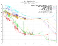
The circuit is just like that from the data sheet, page 17 or so. The noise performance with the power transistor is within 1 dB, compared to the barefoot LT3042. I'm not even sure if the circuit is the culprit if any. Probably one could get rid of the noise peak if the output cap is slightly damped with a series R. A bigger Cout gives a somewhat lower 1/f frequeny of the noise, but a bigger noise peak. The values from the data sheet are a good starting point for experiments. Cset can be increased without detriment. OK, some people will use hilarious values and will note that there are "effects" from the previous experimentation history. The power on switching via power good is your friend. Above Cset = 100uF tantalum there is not much of an improvement. Probably depends on output voltage. Wet slug tantalums AVX 4700uF/25 seem to be an optimum. At 100$ a pop they won't be everybody's darling. Vishay want twice as much.Can you share the noise level measurement setup, and did you do any spectrum measurements ?
At frequencies below 50 HZ, my preamplifier might be partly to blame. (20 * ADA 4898 in par when the pic was taken.)
Just for sure, some people will show up and say "Oh, ah, ceramic capacitors., I'm only lucky with OSCONs hand soldered by a fairie at full moon". I can show them plots of leaky OSCONs that move the 1/f frequency in the KHz range. Oh, not 1/f, more like 1/(f*4). The FFT analyzer has a problem with this, regarding dynamic range. The LT309x Vset IS a high impedance thing.
Input voltage for the measurements were 10 NiMH batteries (14V). They do not add noise of their own. The culprit is the regulator, not Vin, or maybe the pre-amp.
There are more plots at
< >
Cheers, Gerhard
Attachments
Last edited:
IME if these regulators provide the power supplies to DAC/ADC chips they should be placed very close to the load. But if they power the opamps of DAC/ADC boards then regulators on separate boards work quite well.These regulators are most effective when placed closest to the load, on the same board as the DAC/ADC.
I generally like a primary regulation like the Super Regulator (or any other personal preference) and in the DAC/ADC the LT3045/2..
ı have added fast start up resistors.The problem without fast start-up is just that some dacs require that all power supplies are up when the chip is reseted. Without fast start-up the voltage may come up too slow in relation to reset.
Yes you can do it. But you need to select fast switching and high current Transistor and big headsink. Input voltage must be between 16.5-18v. I remember stm have a fast switching high current TR 2SD1047 or BUV48. Already D44h11 is 10A butif you want to more then 5A you can selected high power transistor. But you have to select transistor most close to D44H11.
Many thanks to you for your reply, ok I see, do you have a sample of schematics ? I don't have any experience with this LDO.

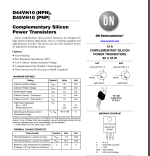
D44VH10 are no longer produced. I was surprised this week that
it already hits TO-220 transistors. Maybe BD239, but that's too
wimpy to drive my crystal oven.
Last summer I was searching TO-3 power transistors to repair my
HP RLC bridge. At Digikey etc virtually nothing, only a few
military / space qualified ones at shocking prices.
Get them while you can.
BTW Lt3042/45 do not have the same pinout. Same functions,
but the LT3045 has 2 more pins IIRC.
Hi all, many thanks to you for your reply, I really appreciate.
So, what's the difference between parallel ICs and using transistor for highest current ?
Best all and thanks again
So, what's the difference between parallel ICs and using transistor for highest current ?
Best all and thanks again
Isn't this just an indication that the local bypass for the ADC is inadequate? All high frequency energy should come right at the chip's pins by the means of enough capacitance. Any impedance between the capacitance and the chip's pins will reduce the effective capacitance, so layout is critical.IME if these regulators provide the power supplies to DAC/ADC chips they should be placed very close to the load. But if they power the opamps of DAC/ADC boards then regulators on separate boards work quite well.
No. LT304x/LT3094 need low ESR/ESL output capacitors due to stability. Larger capacitors (>10uF) do not improve performance. With these regulators using a separate board connected with wires to the load is just asking for trouble (and lower performance).Isn't this just an indication that the local bypass for the ADC is inadequate?
- Home
- Amplifiers
- Power Supplies
- Approaching noiselessness with the LT3045