Hello all, first time posting on the forum, and looking for some help please.
Trying to be quick here, I am not much of an electronics guy, just build amp and preamp kits in the past, kits with instructions, parts and values all lined out. I have always had good results, I follow directions well and try to have good workmanship and safety habits.
Ok, I purchased a PS Tube power supply and a pair of Aikido mono octal boards from Glassware Audio, I have only heard great things about the Aikido! I may be out over my skis here a little.
The first problem I'm having is with the PS Tube power supply, I used the recommended transformer, Hammond 6K56VG, 270-0-270 volt. I followed the directions to the best of my ability, everything seems fine, no blown fuses, nothing smoked lol, the heater voltage is spot on, but am getting 420 vdc at the B+ pad on the board. I have not attached the mono boards to the power supply, so there is no load on the power supply board. I have only left the power on for a minute or two because the 420 vdc seems really high to me, I expected somewhere around 280 vdc. It seems like a lot of transformer, but that is the one Mr. Broskie recommended to me.
I am curious if anyone has used this power supply before, and if so, could you please give me some guidance?
Thanks
Attachments
Hello, and thank you for the reply. I am not at home at the moment, so I can't post pictures of the board right now. I have checked over and over for correct parts and orientation, haven't found any mistakes?
I can list the resistors I've used, it seems the low voltage side works and measures perfectly. I am measuring the B+ with a generic multi meter, measuring between ground pad and the B+ pad.
R3 & R4 100 ohm 1w
R5 2k ohm 5w
R6 300k ohm 1w
R7 100k ohm 1w
Thank you, your help would be most appreciated
I can list the resistors I've used, it seems the low voltage side works and measures perfectly. I am measuring the B+ with a generic multi meter, measuring between ground pad and the B+ pad.
R3 & R4 100 ohm 1w
R5 2k ohm 5w
R6 300k ohm 1w
R7 100k ohm 1w
Thank you, your help would be most appreciated
Can't say I've helped yet. Built a couple of his PS but been awhile.
1. Did you verify the secondary voltages?
2. What rectifier tube are you using?
3. What is the measured VAC at each of the inputs to the rectifier tube?
4. What is the measured VDC output of the rectifier tube?
1. Did you verify the secondary voltages?
2. What rectifier tube are you using?
3. What is the measured VAC at each of the inputs to the rectifier tube?
4. What is the measured VDC output of the rectifier tube?
Hello,
Listed below are the voltage measurements that I get.
House voltage, 121 vac
secondary voltage , 308 vac
secondary voltage after R3 and R4 305 vac
after rectifier and before R5 425 vdc (have used 5AR4 and 5Y3 rectifier tubes, nearly identical results)
after R5 422 vdc
B+ pad 422 vdc
junction between R6 & R7 105 vdc
low voltage side, set up for 12 volts dc, measures at 12.0 vdc
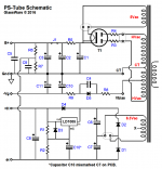
I have a jumper in J1 at the moment, but had a 20H 100 mA choke in J1, didn't change really either way.
Should I be able to power the transformer up, not hooked to the PS-Tube board and check its output directly from the secondaries?
Please let me know if you need any more information, I have removed the PS-Tube board from the transformer to look it over again? I'm at a loss, I keep thinking that I will find some obvious mistake, but nothing so far.
I appreciate you looking at it.
Thanks
Listed below are the voltage measurements that I get.
House voltage, 121 vac
secondary voltage , 308 vac
secondary voltage after R3 and R4 305 vac
after rectifier and before R5 425 vdc (have used 5AR4 and 5Y3 rectifier tubes, nearly identical results)
after R5 422 vdc
B+ pad 422 vdc
junction between R6 & R7 105 vdc
low voltage side, set up for 12 volts dc, measures at 12.0 vdc
I have a jumper in J1 at the moment, but had a 20H 100 mA choke in J1, didn't change really either way.
Should I be able to power the transformer up, not hooked to the PS-Tube board and check its output directly from the secondaries?
Please let me know if you need any more information, I have removed the PS-Tube board from the transformer to look it over again? I'm at a loss, I keep thinking that I will find some obvious mistake, but nothing so far.
I appreciate you looking at it.
Thanks
Attachments
1. agreed on heater winding. Appears to be working as intended.
2. Going to focus on the B+ winding so all questions are in regards to.
a. Is there any distinctive color coding to the B+ secondary windings that differentiate them from amongst themselves?
b. Measuring 308Vac across the B+ secondary seems off. How are you measuring?
Can you take measurements and report back for:
-Neg probe on CT pad and Pos probe on one AC pad
-Neg probe on one AC pad and Pos probe on the other AC pad.
Take measurements with rectifier tube NOT installed. This should effectively remove the power supply board from the transformer.
Last edited:
The B+ secondary windings are three wires, two red and one red with a yellow stripe. Looking at the drawing from Hammond, the two reds are primary and the red with yellow stripe is the center tap.
I have been checking voltage by grounding the negative probe to the ground pad on the board which is grounded to house ground, then checking the various positions with the positive probe, switching the multi meter to appropriate ac or dc setting.
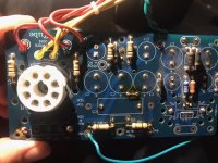
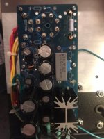
I have disconnected the transformer from the board, I wanted to clean the board, remove the flux, look it over again for poor solder joints, etc....
I will be out of town the next couple of days with work, I will reinstall the board and take the measurements as you requested, but it may be the weekend before I can get it done. I will post my findings asap.
Thanks again.
I have been checking voltage by grounding the negative probe to the ground pad on the board which is grounded to house ground, then checking the various positions with the positive probe, switching the multi meter to appropriate ac or dc setting.
I have disconnected the transformer from the board, I wanted to clean the board, remove the flux, look it over again for poor solder joints, etc....
I will be out of town the next couple of days with work, I will reinstall the board and take the measurements as you requested, but it may be the weekend before I can get it done. I will post my findings asap.
Thanks again.
Quick verification, the red w/ yellow lead is going to the CT pad?
Will keep an eye out for notification once you get the measurements.
Good luck on the trip.
Will keep an eye out for notification once you get the measurements.
Good luck on the trip.
Am I measuring the voltages wrong, by just grounding the neg probe then checking the various pads with the positive probe?
Training trip for work, not always the most fun, lol
Thanks
Training trip for work, not always the most fun, lol
Thanks
When measuring the transformer secondary, want to measure across the entire transformer, so AC pad to AC pad.
Attempting to ascertain if the transformer is hooked up to the input of the rectifier correctly, which it appears to be. The asked for measurements would verify for sure.
Also attempting to figure out the expected output voltage of the transformer. The 6K56VG looks to be designed for 115Vac input with a 540Vac CT output. Step up ratio should be about 4.7 (540/115). Even with a 121Vac input that should be ~570Vac output. The 308Vac measurement has me perplexed as if it were referenced to the CT on the secondary, should be about 285Vac (570/2).
Finally, is there anything in the Aikido board documentation about scrubbing off excess voltage from the PS via a dropping resistor on the B+ input to the board? Dug up an old Aikido pamphlet and he has a table for choosing R12a and R12b to get the right B+ supply to whatever specific tubes were going to be used.
One more thought. The circuit may be working as intended but with a hot transformer. 420Vdc isn't far off, just a little high. If I have the correct formula, for a full wave CT rectifier, Vdc = (Vac CT)/1.43 - Vdrop.
So assuming the 4.7 step up ratio and a 20V drop for a 5Y3GT: (570Vac CT)/1.43 - 20Vdc = 380Vdc.
Given your measurements, the 308Vac reference to the ground (which is tied to CT) would mean a 616Vac CT from the secondary. Vdc = 616/1.43 - 20 = 410Vdc, about what you're measuring. That will get drawn down a little once under load but signal tubes are a small load. If it is the case, not sure why the transformer is stepping up so much given the 270-0-270 expectation. To get 616Vac CT from 121Vac input, step up ratio is about 5.1.
Where'd you get the 6K56VG? Searching Hammond's website didn't yield a datasheet. I did find some similar ones but the 200 series. https://www.hammfg.com/electronics/transformers/classic/200?referer=787
Which leads me to ask, on the transformer you are using, is there 3 leads on the primary side, a white, a grey and a black? Looks like Hammond made some transformers so they could utilize 115Vac or 125Vac inputs. There's a note about using the black lead instead of the gray. Maybe the answer?
Choice #2 (125 VAC Input):
For those customers who are seeing too high a secondary voltage due to higher primary line voltages (roughly 125V input) - use the White & Black wire and tape the gray wire (see schematic).
It is a peak-catching rectifier and a sine voltage. The peak of 270V is 270V*1.414 or 382V.270-0-270 volt...... am getting 420 vdc
That is a 56VA core and I would expect 10% sag, or 10% rise no-load.
Do you possibly have 117V walls at your house? Then 270V*1.414*1.10 is 420V. QED (This would be 449V in my 125V house.)
WITH full load(*) it will sag more than the 10%, and more still due to vacuum rectifier. So you do want 450V capacitors in the HV section to cover the cold-start phase.
(*)A couple Aikidos does not come close to loading that big lump of iron. You may well have 390V-400V at cruise. This is not a problem. The Aikido has two triodes stacked so only 200V on each. All the usual victims are rated 300V or more.

Hello,
The 6K56VG transformer is the one John Broskie recommended to me for use in this application, I bought it a few years back from Allied Electronics...... I thought it seemed like a lot of transformer for a pair of Aikido mono octal boards, but I know little about design and assumed he recommended it for a good reason?
So, I hooked it back up, thought maybe I had found a cold solder joint, but...... same results
CT pad to AC pad, both pads read 308 volts ac
AC pad to AC pad 618 volts ac
Ground to B+ pad 420 volts dc
There are 3 leads on the transformer "in" , two black and one grey, paperwork says the grey is "shield" and is terminated inside the housing on some models, I terminated it at house ground for testing, tried it without the grey wire grounded, no change. I do have 120-124 volts ac at the wall outlet.
I had thought that R5 would pull down the voltage on the PS Tube board, but it doesn't seem to matter if I use 1k or 10 k resistor, same 420 vdc at B+? The mono octal boards have a similar filter on them R12, but 420 vdc from the PS Tube board down to 250 vdc for the octal boards seems like a big step down?
Any help, or ideas would be most appreciated,
Thanks
Series resistors won't reduce the output voltage, unless there is a significant shunt resistor load to ground.
Either use a resistor of a value to simulate the circuit current draw loading, or use the actual circuit.
Either use a resistor of a value to simulate the circuit current draw loading, or use the actual circuit.
Did this ever get resolved? I am betting that there will be a problem in my power supply build as well. I will be building the PS21 power supply for the SRPP+ and there is so little said as to what model to use for this circuit, I just took a shot in the dark. Haven't even sought out a power transformer yet.
Since there are several different tubes that can be used for this circuit, and of course the fact that the circuit can be used for either a headphone amp or preamp, voltage is then determined by the needs of the circuit. So, in this matter, I chose to make a preamplifier since this design will not work as a headphone amp for low impedance phones as well as higher impedance types. My mistake, but no big deal.
I finally chose a 12AU7 tube due to its lower noise and lower MU. No problem. All I have to do is choose which GlassWare power supply will work best for this circuit and tube. It would help us builders immensely if in the 'catalog' the recommended power supply were listed as being a good candidate for this particular circuit.
Start reading here for the short answer: Raw B+ voltage needed for the SRPP+ with this tube is 250-300VDC. B+ after R9 targets the voltage at 250.
I believe that the PS-21 qualifies for this by providing 100-300 Volts depending on power transformer used. Now, the size of the transformer is not given, but I will cross that bridge when I come to it.
You may ask why I continue to build these Glassware kits if it so much trouble for me (and others) to figure them out. Simply put, these kits are the highest quality kits I have ever encountered and sound finer than just about anything else out there. Once I get through the instructional maze, it is still worth it.
The PS-21 can deliver up to 50mA of high voltage and is the prefect choice for a line stage amplifier or a phono preamp.
300V x 0.05A = 15VA. bump it up to a 25VA since that's the next VA Antek offers and gives headroom on the power draw. Can go for overkill and get a 50VA one.
Thank you so much for this information. I admire these kits so much that I made one of the phono preamps as a tribute to my father. Damned thing is the best that I ever had. Then there was the tube Aikido headphone amp that I made for my son. That was years ago and he still brags about it. The thing that scares me is that this preamp will be good enough to replace an already fantastic preamp that I have in my system.
I think that the Antek 25VA will accomplish the most that I could ever appreciate. If this thing goes well, I may have photos to boast with.
Ideally, I need a transformer that has secondaries for both High voltage (500 VCT, 300 V), and another secondary for low voltage (12 V, 2.5A). Didn't see any at Antec or Hammond. Strangely, Hammond only offers 6.3 heater windings.
Last edited:
- Home
- Amplifiers
- Power Supplies
- Glassware PS Tube HELP