Good day folks,
Been pulling my hair out with this one. Amplifier came in, in protect. No shorts found, powered up and confirmed unit going into protect.
Noticed brief DC at the L-ch Spk terminal. Disabled the protection and powered up, unit powered up ok, good rails and regulated LV supplies. L-ch measures +62vdc across the speaker terminals. Inserted audio and r-ch passed clean audio.
Began troubleshooting and didn’t find any defective components in circuit for the L-ch. pulled both pre drivers B631k/D600 out of circuit and these tested ok. Replaced with new and DC went away.
Unit passed clean audio, reassembled and loaded unit, around 65deg C, unit went into protect. When checked, DC at L-ch Spk terminals again.
Continued troubleshooting, this time replaced all components from the differential pairs to the pre drivers, unit still has DC at L-ch Spk terminals.
I’ve been using the schematic attached in the below thread, this seems to be most accurate.
Anyone got a remedy for all components testing ok and DC at the Spk terminals?
https://www.diyaudio.com/community/threads/orion-xtr-2000-2-output-transistors.382338/
Attachments

Does it always have DC (even when cold)?
Do you see any DC into the differential amplifier?
Does it cause excessive current draw when a load is touched to the speaker terminals or does the voltage simply drain away?
Do you see any DC into the differential amplifier?
Does it cause excessive current draw when a load is touched to the speaker terminals or does the voltage simply drain away?
Does it always have DC (even when cold)?
Do you see any DC into the differential amplifier?
Does it cause excessive current draw when a load is touched to the speaker terminals or does the voltage simply drain away?
Yes, this was the initial problem, after troubleshooting and everything testing good in circuit, I replaced the pre driver pair B631K/D600, the unit worked and I proceeded to load test, this is where it worked up until around 65 deg and it went into protect.
Do you see any DC into the differential amplifier?
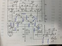
yes, I am seeing some strange DC values, if I remove the component it tests ok out of circuit, replaced the components with new and the DC values measured are the same. I've attached a copy of the clarion schematic and placed the respective DC values I'm measuring alongside the corresponding component. All are taken with respect to power terminal ground, with RCAs- no audio connected.
Does it cause excessive current draw when a load is touched to the speaker terminals or does the voltage simply drain away?
with a load connected it draws high current and pulls the PS down.
Attachments
Is R49 within tolerance?
Do you have the base and emitter voltages backwards for Q2?
Did you check for open junctions or leakage for Q2?
Do you have the base and emitter voltages backwards for Q2?
Did you check for open junctions or leakage for Q2?
Is R49 within tolerance?
Do you have the base and emitter voltages backwards for Q2?
Did you check for open junctions or leakage for Q2?
Yes, it measures 998ohms
Do you have the base and emitter voltages backwards for Q2?
no I remeasured with your asking and its the same, it tested good on diode check, no leakage out of circuit. I just swapped it with Q2 from the R-ch and the voltages remain the same. I've also checked continuity between those transistors in the differential pair and its ok.
Did you check for open junctions or leakage for Q2?
According to your diagram, one side of the resistor is at +13.3 and the other side is at -14.6. How do you get 0.006v?
yes, as you mentioned it I'm seeing this disparity, these voltages are with the negative lead on the negative power terminal. i confirmed 0.006 across R49.
I'm tracing through the circuit to see where/why this is happening.
I'm tracing through the circuit to see where/why this is happening.
I did some tracing and troubleshooting, this is what I found:
i removed all four transistors from the diff. pairs, all tested good out of circuit. I powered and compared voltages with the R-ch for the Q2, this seems to be working correctly and the -14.6 measured at the collector is being cascaded down from higher up in the circuit.
B to C measures; R-ch around 8mega ohms, on the L-ch, it measures 1.9kohm. I've removed Q9, Q10, Q11 from the circuit and the resistance is still there.Comparing resistances with the working R-ch, the only disparity I'm finding is Q9 (B631K),
The PCB isn't burnt, I'm sorta leaning to this PCB is conductive.... this amplifier operates at +/- 72v rails.Without Q5, Q6, Q7, Q8, Q9, Q10, Q11, Q12, Q13, i still measure 1.9kohm on the B/C pads of Q9. I've cleaned thoroughly with alcohol and dried with the heat gun, I've also soldered two wires to the B/C pads and applied 30v with PS, I didn't measure any current draw and nothing heated up. I now measure 3.9kohms between the B/C pads of Q9.
all transistors Q5 to Q13 were tested ok and resoldered to PCB, powered up and voila, +62vdc at the L-ch spk terminal again.😡
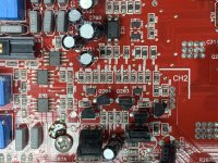
Attachments
Either remove the optocoupler or solder a bridge across its diode (pins 1 and 2). Do you still have DC on the output?
Did you pull D7 and check it for leakage?
Did you pull D7 and check it for leakage?
Either remove the optocoupler or solder a bridge across its diode (pins 1 and 2). Do you still have DC on the output?
No sir, I suspected c25 and c26 in the earlies, they both tested good in and out of circuit.
The resistance 1.9kohms is there with or without them in circuit.
I tried powering with both omitted from the circuit and the DC persists.
I’ve replaced them with through hole 101 pieces with no luck.
The resistance 1.9kohms is there with or without them in circuit.
I tried powering with both omitted from the circuit and the DC persists.
I’ve replaced them with through hole 101 pieces with no luck.
Did it have DC when the differential transistors were out of the circuit (the rest of the components n the circuit)?
- Home
- General Interest
- Car Audio
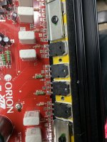
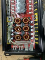
- Orion XTR2500.2 DC at Spk terminals