I have been rebuilding an old Pioneer SM-R150 amp from the 60's. I got it running with the old paper in oil caps replaced, and it is possible to listen to it, but there is a lot of hiss, the sound is not great, and very crackly pots indicating some DC getting to them, or major cleaning needed.
I described the amp here ...
DiyAudio - Pioneer SM-R150
I decided I do not need inputs for tape heads and crystal cartridges. In order to create something functional for today I have decided to take the 3 inputs and have Phono and two Aux. In addition to volume, it has a balance, bass and treble controls, as well as a switch for stereo/mono (both channels)/mono(one channel). I have decided I will replace the 3rd option on the stereo/mono switch with 'Direct' so the audio path can skip the balance and tone controls.
The output stage is simple (uses 6AR5 tubes, a 6K6GT in a 7-pin package) and does not need any changes. The tone stack could be better implemented as a Baxendall type stage, and I have shamelessly cloned the one from this thread:
DiyAudio - Baxendall Active Tone Control
Now I need to fianalise how the Phono stage should look. I have narrowed it down to 3 options:
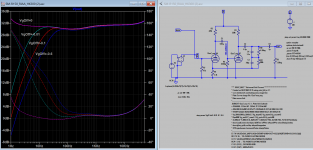
The first problem is I am not 100% sure what that simulation is telling me. What is an optimum set of curves, and what is acceptable? Is that phase shift on the right axes, and what is a good metric? I will only be using the existing 12AX7 tubes with the reworked phono stage, so it just has to be good; great is for another day - I need my kitchen table back!
First up is the original Phono stage, which had switched equalisations for different sources and a 30K load resistor at the input, which I have changed to the standard 47K one. It uses an active RIAA equalisation, and to my untrained eye it does not seem to do too bad a job.


Next up is the ValeWizard version of the RCA Phono stage:


Finally the HK A300. I include it here because I have used the same approach to simulate this phono stage, and I must be doing something wrong because the curves out are very different, and I am not knowledgeable enough to deduce why. I would really appreciate some input on how to interpet this approach for analysing the RIAA equalisation.


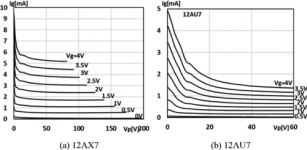
I have included the LTSpice files, and I am using tube models from Ayumi Nakabayashi.
I described the amp here ...
DiyAudio - Pioneer SM-R150
I decided I do not need inputs for tape heads and crystal cartridges. In order to create something functional for today I have decided to take the 3 inputs and have Phono and two Aux. In addition to volume, it has a balance, bass and treble controls, as well as a switch for stereo/mono (both channels)/mono(one channel). I have decided I will replace the 3rd option on the stereo/mono switch with 'Direct' so the audio path can skip the balance and tone controls.
The output stage is simple (uses 6AR5 tubes, a 6K6GT in a 7-pin package) and does not need any changes. The tone stack could be better implemented as a Baxendall type stage, and I have shamelessly cloned the one from this thread:
DiyAudio - Baxendall Active Tone Control
Now I need to fianalise how the Phono stage should look. I have narrowed it down to 3 options:
- The original Phono stage, which did not get a good rap on the thread where I discussed the amp.
- The ValveWizard version of the classic RCA Phono stage
- The Harman Kardon A-300 phono stage (as promoted on the AngelFire HK A-300 site, which is a source of tuition marterial for LTSpice and amp design)
The first problem is I am not 100% sure what that simulation is telling me. What is an optimum set of curves, and what is acceptable? Is that phase shift on the right axes, and what is a good metric? I will only be using the existing 12AX7 tubes with the reworked phono stage, so it just has to be good; great is for another day - I need my kitchen table back!
First up is the original Phono stage, which had switched equalisations for different sources and a 30K load resistor at the input, which I have changed to the standard 47K one. It uses an active RIAA equalisation, and to my untrained eye it does not seem to do too bad a job.
Next up is the ValeWizard version of the RCA Phono stage:
Finally the HK A300. I include it here because I have used the same approach to simulate this phono stage, and I must be doing something wrong because the curves out are very different, and I am not knowledgeable enough to deduce why. I would really appreciate some input on how to interpet this approach for analysing the RIAA equalisation.
I have included the LTSpice files, and I am using tube models from Ayumi Nakabayashi.
Attachments
#1) The Bode plot for HK A300 has a vastly different scale for the Y-axis, extremely magnified compared to the other two.Finally the HK A300. I include it here because I have used the same approach to simulate this phono stage, and I must be doing something wrong because the curves out are very different, and I am not knowledgeable enough to deduce why. I would really appreciate some input on how to interpet this approach for analysing the RIAA equalisation.
#2) The unexpected rise at low frequencies is due to C2 coupling cap between 2nd triode plate and RIAA network being way too small; need at least 0.1u or better 1uF. Compare to circuit #1 which has 0.1u.
#3) I don't know any set of spice parameters which can handle grid-leak-bias; Ayumi's are no exception; they usually resolve the grid to be 5pV or so when it should be around -1V; which causes the plate voltage to drop to 30V in your circuit.

It has more to do with grid current model rather than LTSpice ability to resolve. As you would have noticed AY model assumed VgOff (min.) always zero and therefore do not process below zero, only while the grid is positive, it's cut off at zero (at the point while point the input Z is incorrect of course). To prove that is so here is 12AX7_MAZ (Mazda) Paint Tool model with Advance Grid Current model you can try.
Attachments
Last edited: