Trying to troubleshoot what might be a bad power supply, and it looks like one of my 300B tubes is toast ;-(
Have one last reasonably good pair but don't want to exert much stress on any as they are not inexpensive these days.
noticed after a very short run one channel's tube was very hot to the touch, while the other channel was room temp..
Strange as I could hear zero difference in the music between the channels..
May be a runaway tube, don't want to sacrifice another while finding out...
back in the good old days when the amp was working reasonably well, the cathode resistor at 1k ohm had a drop of 78V, so put 78mA through the plate to cathode.
Seeing I had a 375v drop plate to cathode, I figure 4.8K ohms is about what the 300B presented to the DC side of things....
1) For testing the PS, is using a 5k 20w resistor from plate to cathodes sound like a reasonable way to duplicate ?
2) Given B+ was 450v (plate to ground) with the 300B in place, what would you folks expect the B+ to be with the 300B tubes removed ?
Thanks !
EDIT!
I just realized I need at least 30w, that said (2) 10k 20W in parallel or 1 5k 40w. My question is really to test PS voltages after warm up and see what the DC looks like)
Last edited:
Use a resistor load equal to 450V divided by the sum of all plate currents drawn by all tubes connected to B+.
Then the B+ should not change without the tubes.
Then the B+ should not change without the tubes.

Are you sure, that PSU occurs tube failures?
"one channel's tube was very hot to the touch, while the other channel was room temp"
If it was a few seconds after switching on, the defected tube will be very hot.
If there is runaway, the voltage on 1k of "bad" channel must be mostly different from other channel voltage.
Try to measure both voltage (for a few seconds!).
If its -mostly- different, remove coupling capacitors from 300B grids, and repeat measuring.
If now the bias voltages -almost- equal, one of coupling capacitor leaking.
If the bias voltages -mostly- different, the cathode R//C or the grid leaking resistor ruined.
If the cathode blocking capacitor (paralleled by 1k) is leaking, partially shunting 1k, so cathode bias "resistor" value decreasing, which occurs growing anode current.
If the grid leaking resistor (from 300B grid to ground) is bad, tube has indefinite bias voltage, so runaway can be created.
euro21,
No Im not sure of whats happening, but the likely culprit to me is the PS.
All passives in the 300B B+ path replaced with mouser or digikey components and all have higher rating than required.
TY regarding very hot tube likely being the side to worry about.
I did notice considerable differences on the cathode resistor 2 times, kind of spuratic though.
Wasn't sure if it was my error the first time I saw it, like may be I had something set up wrong or...
What I saw the 2nd time (a few days later) was 140 volt drop on one cathode and 30 or 40 drop on the other ????
To me this meant 1) run away on one tube consuming all the power the supply could give, OR I wondered if a bad PS could over volt one side while under volting the other...
That said, I have been plagued with strange occurrences from time to time simply want to load the power supply down for a few hours without toasting a tube..
Also, I now realize I need a 30w resistor at a minimum, and probably should go much higher...
If anything I have mentioned strike a knee jerk reaction, please let me know.. I want my SE 300B back in service BADLY..
Create an accurate complete schematic, and post it.
A schematic is worth 1,000 posts that attempt to guess the cause of the problem.
Without a schematic, we might as well be Blindfolded Archers, trying to hit the target.
Or call your car dealer, describe the mysterious car sound over the phone, and hope he knows what is happening.
A schematic is worth 1,000 posts that attempt to guess the cause of the problem.
Without a schematic, we might as well be Blindfolded Archers, trying to hit the target.
Or call your car dealer, describe the mysterious car sound over the phone, and hope he knows what is happening.
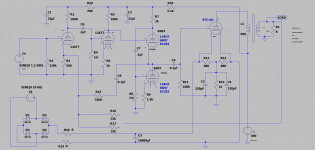
What is the voltage rating of C9 coupling cap to the 300B grid?
What is the brand and model of C9?
Is this a stereo amp, or do you have mono blocks?
One of the channels works, right?
For the working channel:
What is the DC voltage at the left side of C9?
What is the DC voltage at the right side of C9?
What is the DCR of L1?
What is the DC voltage on R14?
is B+ 490V?
is the 300B plate 430V?
What is the resistance of R18 and R19 (Caution, turn amp off, wait until B+ discharges, take out the 300B to measure R18 and R19).
Be sure to plug the 300B back in before powering the amp on again, or else a large transient of about 8V to 10V from 10,000 uF will hit the 300B filament Vary hard.
Are you sure, that values (resistors, voltages) in the power stage of schematic are valid?

Yesterday I finally ordered the (2) 50w 5.6k resistors, but since its the weekend I have a few hours to myself....
Does everyone think its safe to power the amp up with the 300B's in place in short intervals (Making sure all caps are discharged and all cooled off) ?
I definitely need help on this, afraid to ruin any more tubes. I suffer from lack of patience at this point my much preferred amp out of the loop for way too long...
If its safe I will work towards answering all the questions above....
Update...
Zero input signal, R8 dummy loads on the 8 Ohm speaker taps...
Without the 300B's in place I measured under 15 milli volts from the grid (pin 3) to ground.
Bounced around a little, the settled number was under 8mV on both channels.
Dont believe I have any dc leakage at least up to the 300B's...
I cant explain why I saw very, very, large differences in the voltage drop across cathode resistors, and will be investigated when my power resistors get here.
Again, I believe when it gets really warm is when the main issue rears its head....
In the mean while, I did find that my figuring for reducing the filament voltage worked perfect on one channel and a little too much (5v-4.1)on the other !
I believe I have another thread on that, will post my dilemma and findings there..
The left side of the amp has a 4v-dc filament voltage (under load) and the 1k ohm cathode resistor had a voltage drop of 50V.
The right side has a 5v-dc filament voltage (under load) and a 70v drop across its 1k ohm cathode resistor.
Swapping tubes made zero difference, the left side cathode resistor v-drop is always lower..
I think swapping the 300bs ruled out a bad filament in one or the other, and also ruled out
Would a 1v difference in filament voltage cause cathode voltage drop difference of 20V ?
Pull out 300B tubes and HT rectifier tube (if it's available) to discontinue HT.
Try to swap both 300B filament with 4R 10-25W Resistor (5V/1.25A).
Measure both filament voltage.
If its different, on the lower side R18, R19, R12, R13 or the graetz is defected.
Are you sure, that R12, R13 is 680R?
Try to swap both 300B filament with 4R 10-25W Resistor (5V/1.25A).
Measure both filament voltage.
If its different, on the lower side R18, R19, R12, R13 or the graetz is defected.
Are you sure, that R12, R13 is 680R?
4R is always available, 4.16R (5V/1.2A) is rare.
For testing 4R is acceptable.
If you want to precise settings, try to use 6-8R wirewound potentiometer (set to 4.166).
For testing 4R is acceptable.
If you want to precise settings, try to use 6-8R wirewound potentiometer (set to 4.166).
Great catch! No, R12 and R13 are 24Ohm!Are you sure, that R12, R13 is 680R?
Updated the schematic.. TY
If I use my bench voltage regulator to say 5v, and actually measure current through the 300b filament (while not installed, simply on the bench) wouldn't I be able to measure accurately the resistance of the tubes themselves ?
Also in the post previous, you wrote "graetz"
What is that?
Graetz: https://en.wikipedia.org/wiki/Diode_bridge
If you tried 300B filament with 5V bench supply and this measured current too (1.2A +/- 100...150mA), possible calculating the "hot" resistance of filament (Ohm's law).
Try to use this "5V" (if bench supply "cold" output point is independent from safety earth of bench supply) instead of built in raw supply.
A 300B with only 4V across the filament will draw less filament current . . .
Versus the same 300B in the same circuit, but with 5V across the filament.
300B cold filament is about 1 Ohm. It will emit No electrons, no plate current.
300B warm filament with 5V across it is 4 Ohms. It will emit lots of electrons; gives expected current versus the plate / grid graph curves.
300B cool filament with 4V across it is between 1 Ohm and 4 Ohm; but it will emit far less electrons; will not meet the plate / grid graph curves.
So, with my bench power supply I sent 5v directly to the 300B filaments,
cold and on the bench, 1 tube drew 1.18Amps and the other drew 1.2 amps.
That said, I don't believe those tubes would cause a 1 volt difference in the filament.
All 8 diodes just changed out with parts directly from Mouser.. Went from 5404's of unknown origin to VISHAY SB540's
Used the diode function of my DMM and grouped the 8 closest matching I could from the 25 or so I ordered...
Same with the cap, went from 6800uf 16V to 10000uf 35V . Everything up-sized in wattage and voltage requirements since I was there already.
Again, this is the same exact path I went down before tearing into it. That said the voltages were higher. but both off from each other.
I could swear I had the filament voltages dialed in. When I first powered up, I felt happy that I actually figured something right.
I just feel like under load, something changes.
Gonna see if anything looks strange on the AC before the diodes.
Is there any way to check a PS or OPT using a megaohm meter ?
Try to test filament powers with 4R resistor instead of 300B filament.
I put banana plug wires to socket for test.
I put banana plug wires to socket for test.
Disconnected the PS 5v ac supply to the pcb on both channels. hooked up my variac and recorded what output voltage was needed to see 5v dc at the filaments on both channels...
I wrote the voltages down, too lazy to go to the bench and cant remember, but the left channel definitely needed more voltage on the raw ac side... there is something defiantly different between both heater circuits..
Its kicking my but. I know I bench tested the pcb before reinstalling and was 100% I Remember testing directly after all was good...
I may build separate off board rectification and filter circuit for both channels and see how that works..
Or..
install the Colman filament regulator kit I was saving for a future 300B build
After finding 1 horrible and 1 bad soldering job by yours truly, both filaments for the 300B are now 5V!
Voltage drop across both cathode resistors (1kohm) is 72V..
Almost HOME hahaha...
Voltage drop across both cathode resistors (1kohm) is 72V..
Almost HOME hahaha...
- Home
- Amplifiers
- Tubes / Valves
- 300B B+ load on power supply