Good evening,
I have a Orion XTR1400.1D.
It was in use for maybe a year. I bought it new but not in the box or at least told it was new.
The batteries on my truck died and I assume they killed the amp when it was boosted.
I have been reading as much as possible to figure out what to test.
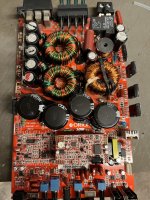
It’s very obvious that the transistors blew up. Smoke/smell/burn marks. I had no output but the amp had the light on but not the protection light. No fuses blew it has 4 30 amp fuses on the amp.
I attempted to replace and they simply blew up again.
I am going to order more but would like to not run in circles replacing random parts. It’s obvious they were defective.
I have another amp that functioned torn apart to replace one of the potentiometers on it and am trying to use it to compare readings.
I think I have a dead short in the amp somewhere as I have continuity between positive and negative terminals and my other test amp is not like this.
None of the capacitors are swollen. I have tried checking the transformer for shorts and can’t seem to find anything wrong.
I have a soldering iron, soldering pump, I just ordered an oscilloscope should be in the next couple days.
I have a multimeter as well.
I’ll post a picture of the blown up internals tomorrow when I get a second.
I would appreciate any help
I have a Orion XTR1400.1D.
It was in use for maybe a year. I bought it new but not in the box or at least told it was new.
The batteries on my truck died and I assume they killed the amp when it was boosted.
I have been reading as much as possible to figure out what to test.
It’s very obvious that the transistors blew up. Smoke/smell/burn marks. I had no output but the amp had the light on but not the protection light. No fuses blew it has 4 30 amp fuses on the amp.
I attempted to replace and they simply blew up again.
I am going to order more but would like to not run in circles replacing random parts. It’s obvious they were defective.
I have another amp that functioned torn apart to replace one of the potentiometers on it and am trying to use it to compare readings.
I think I have a dead short in the amp somewhere as I have continuity between positive and negative terminals and my other test amp is not like this.
None of the capacitors are swollen. I have tried checking the transformer for shorts and can’t seem to find anything wrong.
I have a soldering iron, soldering pump, I just ordered an oscilloscope should be in the next couple days.
I have a multimeter as well.
I’ll post a picture of the blown up internals tomorrow when I get a second.
I would appreciate any help
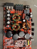
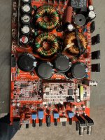
Here are some pictures.
Attachments
-
 368E2EA9-21D7-4C0C-842F-FC8C8314859F.jpeg710.4 KB · Views: 70
 -
 22985FCC-99C0-4BFD-B9B4-8767FE1AAB52.jpeg748.5 KB · Views: 80
 -
 AF167524-BEE0-456D-BE58-D93228518A8C.jpeg540.3 KB · Views: 72
 -
 DB5A67BB-34FC-4780-8E82-80419D2DB486.jpeg705.7 KB · Views: 71
 -
 E5D81123-097E-4988-A344-EE3CD8016496.jpeg141.6 KB · Views: 71
The term 'continuity' is vague. It's best to use ohms or diode-check and state the precise reading on the meter's display.
There is a lot of via damage shown on the FETs. You may have to solder both top and bottom on those connection (and possibly more) to re-establish good connections.
Do you know how to use a scope?
Are you sure that there are no solder bridges on the connections you desoldered?
There is a lot of via damage shown on the FETs. You may have to solder both top and bottom on those connection (and possibly more) to re-establish good connections.
Do you know how to use a scope?
Are you sure that there are no solder bridges on the connections you desoldered?
Hi Perry
I have looked up online briefly to learn how to use the oscilloscope. I have managed to get readings on where the transistors are.
One is 5 volts and the other reading is 12 v
I agree there is a lot of damage
I am going to clean up the soldering and try and get some of the soot off to clearly see the board.
I am not pleased with the soldering job.
The second blow up beat up the chip quite a bit.
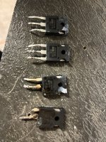
Based on one of your posts I believe I had a bipolar transistor ? that is toasted. I’m thinking this may have caused the greif.
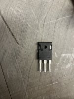
I have attached a picture of the transistor that I believe is defective.
I’m going to order a few more transistors to replace them.
I have looked up online briefly to learn how to use the oscilloscope. I have managed to get readings on where the transistors are.
One is 5 volts and the other reading is 12 v
I agree there is a lot of damage
I am going to clean up the soldering and try and get some of the soot off to clearly see the board.
I am not pleased with the soldering job.
The second blow up beat up the chip quite a bit.
Based on one of your posts I believe I had a bipolar transistor ? that is toasted. I’m thinking this may have caused the greif.
I have attached a picture of the transistor that I believe is defective.
I’m going to order a few more transistors to replace them.
Attachments
Wait until you get the scope to check the drive signals. A multimeter can be used but it's not definitive.
That's a rectifier in the photo.
Read through the following page for basic scope usage.
https://www.bcae1.com/oscope.htm
That's a rectifier in the photo.
Read through the following page for basic scope usage.
https://www.bcae1.com/oscope.htm

HI Perry
I Removed the original solder and cleaned the board as good as possible and installed new Transistors as well as a new rectifier.
My oscilloscope showed 24 vdc and 5.3 vdc when i tested it.
I have installed it and tested. it works great
Thank you for the assistance.
I Removed the original solder and cleaned the board as good as possible and installed new Transistors as well as a new rectifier.
My oscilloscope showed 24 vdc and 5.3 vdc when i tested it.
I have installed it and tested. it works great
Thank you for the assistance.