Some years ago I built 801/801a/10/10Y preamp.
I'm a fan of thoriated tungsten (TT) filament tubes (was made in the first half of the last century), collected its for decades.
I've been using it daily for six years, satisfied.

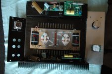
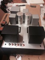
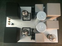
It's two box design, HT and LT supply, and preamp box.
I use 801 graphite anode, ceramic base Radiotron.
It's (801) has a little lower power than later developed 801a, but as preamplifier it's irrelevant.
The design can work with 801/801a (military sign VT62) or 10/10Y (military sign VT25). The VT25A also can work, but it's not TT tube (oxide coated filament).
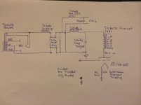
The tube is "gyrator" loaded, filament biased. The filament regulator designed by Rod Coleman (V4, later changed to V7).

The gyrator is early prototype of Ale Moglia design.

The HT PSU working with AZ1 mesh anode rectifier, c-L-C-L-C design.

The LT raw supply C-r-CMC-C type.

The PSU box is simple, I put it at the bottom of the rack.
It's powered up with common switch of HiFi rack.
The ramp of AZ1 enough slow for heating the DHT preamp tubes.
The amplifier box made using a prefabricated chinese box.
I usually use these heatsinked boxes for build. The quality is enough good and price (was) enough cheap.
The side heatsink cooling the filament bias resistor, the R.C. regulator and the gyrator.

The inner space is a little narrow, so the wiring is "neurotic" too. 🙂

I'm a fan of thoriated tungsten (TT) filament tubes (was made in the first half of the last century), collected its for decades.
I've been using it daily for six years, satisfied.
It's two box design, HT and LT supply, and preamp box.
I use 801 graphite anode, ceramic base Radiotron.
It's (801) has a little lower power than later developed 801a, but as preamplifier it's irrelevant.
The design can work with 801/801a (military sign VT62) or 10/10Y (military sign VT25). The VT25A also can work, but it's not TT tube (oxide coated filament).
The tube is "gyrator" loaded, filament biased. The filament regulator designed by Rod Coleman (V4, later changed to V7).
The gyrator is early prototype of Ale Moglia design.
The HT PSU working with AZ1 mesh anode rectifier, c-L-C-L-C design.
The LT raw supply C-r-CMC-C type.
The PSU box is simple, I put it at the bottom of the rack.
It's powered up with common switch of HiFi rack.
The ramp of AZ1 enough slow for heating the DHT preamp tubes.
The amplifier box made using a prefabricated chinese box.
I usually use these heatsinked boxes for build. The quality is enough good and price (was) enough cheap.
The side heatsink cooling the filament bias resistor, the R.C. regulator and the gyrator.
The inner space is a little narrow, so the wiring is "neurotic" too. 🙂
Attachments

Perfect candidate for a SE Zotl power amp... (i have tried it once)
https://www.diyaudio.com/community/threads/zotl-and-ferrites.73135/post-5665492
https://www.diyaudio.com/community/threads/zotl-and-ferrites.73135/post-5665492
Here's what I'm using. I've attached 2 versions, first an "idealised" circuit for my 2a3 amp. The second is what I'm actually using since I have a separate PSU for my 10Y input stage. I like resistor loads for their purity and tonality, and I use filament bias which is cleaner than using a cathode bypass cap. The Hammond 1140-LN-C is a good quality broadcast SUT and in 1:4 it gives me enough overall gain to use just 2 stages in my amp.


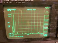
Some -live- measurement (from '16).
Bandwidth is enough good.

FFT spectrum (2V RMS output).

Hum (50Hz) at about -100dB, the distortion as expected.
Without input signal.

The 8-20kHz components caused by (EMU0404 USB) soundcard.
The measured output impedance (at 1kHz) is 920R.
Bandwidth is enough good.
FFT spectrum (2V RMS output).
Hum (50Hz) at about -100dB, the distortion as expected.
Without input signal.
The 8-20kHz components caused by (EMU0404 USB) soundcard.
The measured output impedance (at 1kHz) is 920R.
I built a similar one (gyrator+coleman v7) but 7.5V for filament directly, with 410ohm tx2575 as R3.
IMHO 801a is much easier to handle/select than cx-301a.
Recently I added a source follower after in order to drive the power follower from audiodesignguide.com (input capacity of 2000pf without the gain stage).
IMHO 801a is much easier to handle/select than cx-301a.
Recently I added a source follower after in order to drive the power follower from audiodesignguide.com (input capacity of 2000pf without the gain stage).
Euro21, I would sure like to find one of those scarce 801 versions! For now, I only have two pairs of "simple" 10Ys to play around with 😊
I have been trying to simulate my setup using Ale's gyrator and source follower + the Sowther 9063 (4:1) with LTspice . Would it be too much if I ask for your spice models for them?
I have been trying to simulate my setup using Ale's gyrator and source follower + the Sowther 9063 (4:1) with LTspice . Would it be too much if I ask for your spice models for them?
Thank you very much, I really appreciate it!
I have made a model for the gyrator, but I have found (with my little experience with LTspice) more difficult to find the mosfet models and trust the circuit. Still much to learn about LTspice....
I have made a model for the gyrator, but I have found (with my little experience with LTspice) more difficult to find the mosfet models and trust the circuit. Still much to learn about LTspice....

Very nice stuff here!
What's the thing with the Coleman filament supply? Why is the cathode bias resistor part of the heater current loop?
What's the thing with the Coleman filament supply? Why is the cathode bias resistor part of the heater current loop?
Ahhh... Coleman fixes the current, so the cathode bias is fixed by the current in the resistor. Makes sense, but it needs a high-power cathode resistor to cope with the filament current running through the resistor.It's called filament bias. That way you avoid the bypass cap. Thomas Mayer helped popularise it. Works wonderfully well with the Coleman Reg V9.
Can't we live with much less heat from the cathode resistor? Assume the cathode bias resistor is not in the loop of the filament current (Coleman regulator connected directly on the filament pins). The cathode resistor would see only the anode current from the tube, not the filament current. The Moglia Gyrator fixes the current through the tube, so the current in the cathode resistor is also fixed, and hence the cathode voltage is held constant, too. No AC/audio signal on the cathode. No need for a bypass cap either.
What am I missing?
You're not missing anything except personal preferences. I use a resistor load on the anode because I find it a purer sound than a gyrator on the music which I listen to, jazz and a lot of classical and opera. Purity of tone is important to me. May be less important on rock music but that's not my bag.
Yes, the resistor is bigger and gets hot. That's just the way it is. Not something that bothers me - I put the resistors on the top plate so they don't fry the interior. I find the 10Y sounds good this way, together with the 26 and a few others. Chacun à son goût.
Yes, the resistor is bigger and gets hot. That's just the way it is. Not something that bothers me - I put the resistors on the top plate so they don't fry the interior. I find the 10Y sounds good this way, together with the 26 and a few others. Chacun à son goût.
Two things...What am I missing?
One is that the constant current assumed for the anode load: it is a good current source, but is limited by the gm (mA/V) of the lower FET. So the impedance is not infinite. Meanwhile, the cathode resistor for 20mA @10V bias is 500 Ohms; this will raise the ra of the 10Y by ca. 3500 Ohms, in addition to it's normal value. So the distortion will increase a little.
More seriously, the unbypassed Rk in any DHT will increase the noise at the mains fundamental (50/60Hz) due to leakage current through the mains transformer. This is true for any method of heating from the mains. The current is common mode and depends only upon the mains voltage and the leakage capacitance. With a good EI, the leakage is about 10uA at 230V rms. There are no practical methods of suppressing this noise, other than putting the bypass capacitor back in, or reverting to filament bias.
Thanks for these insights!
...or connecting the cathode (one end of the filament) directly to GND and apply fixed bias to the grid. 😀...There are no practical methods of suppressing this noise, other than putting the bypass capacitor back in, or reverting to filament bias
Yes, grid bias is the best way to bias a 10Y, so long as the voltage is quiet and stable. And it allows higher Va & -Vg for more input headroom.
- Home
- Amplifiers
- Tubes / Valves
- 801a tube preamp