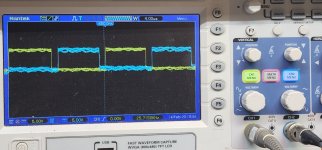
The DC on pin 4 could be causing the deadtime. I'd expect it to be about 1/3 of that voltage from a generic diagram values.
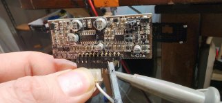
Zooming in on your image, I think R27 (connected between pin 4 and ground) appears to be a 15k. That would make the voltage a bit higher than the normal 10k but 150mv still seems high. Check the value of R23 and R27 (pull them) and you may want to lift one terminal of C24 to see if that affects the voltage on pin 4 (with the resistors in the circuit).
I wouldn't expect this to cause the FETs to heat up. It's likely to have the opposite effect. Under load, I wouldn't be surprised if the primary filter caps would overheat.
The voltage on pin 3 of the 494 is another input that can cause the amp to have excessive deadtime.
If you connect pin 3 to pin 7 on the 494, does the pulse width increase?
What is the marking on R28 of your board?
The voltage on pin 3 of the 494 is another input that can cause the amp to have excessive deadtime.
If you connect pin 3 to pin 7 on the 494, does the pulse width increase?
What is the marking on R28 of your board?
- Home
- General Interest
- Car Audio
- Power supply card