I wonder how much inductance is in typical headphone. Say a 32 Ohm device. Or other.
Somebody must have possibility to measure inductance.
Do you know?
Somebody must have possibility to measure inductance.
Do you know?
I am designing a headphones circuit in my SPICE.
I want to simulate a headphone with resistor and inductor to be able to see if my circuit works with that.
I will add a Zobel filter with RC to make the circuit stable at inductive load.
I want to simulate a headphone with resistor and inductor to be able to see if my circuit works with that.
I will add a Zobel filter with RC to make the circuit stable at inductive load.
What can I tell you... They're really bad. No highs beyond 10k.
My Superlux HD 668B are 4.8uH, 60 ohm.
My Superlux HD 668B are 4.8uH, 60 ohm.
Never thought about that. Just tested a set of Samsung OEM earbuds. 32 ohm and 0.122 mH.
Frequency response as measured shrink wrapped to my UMIK 1. The inductance explains a lot, come to think of it.
That is more like it.What can I tell you... They're really bad. No highs beyond 10k.
My Superlux HD 668B are 4.8uH, 60 ohm.
60 Ohm 4.8uH
I have tested 1-2-3-5 uH in my circuit. With 32 Ohm.
And I managed to set up a rather good RC filter for those.
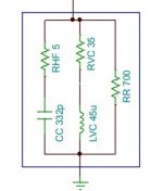
That's a model for motional impedance - not quite the same thing. a more accurate total load, but only for whatever ...headphoney-thing that particular model was based upon.
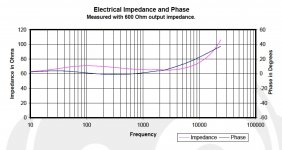
You can calculate the lumped inductance quickly by just by looking at measurement curves of impedance, and the impedance rise between average impedance, and the top -end. I also still think Tyll at Inner fidelity did the best job of anyone on the comparable-measurement front, and since anyone can download the entire archive I suggest you start there.*
Let's take a headphone I really like, the AKG701: which is also inherently so well damped it makes teh explaining easy.
Impedance plot is attached below; from 65ohms wideband to VC inductance adding c. 42ohms by 25Khz calculates out at 250uH: L = delta z / (2* pi*f) [ though actually you can finesse the estimate a lot since we know source imepdance on test - 600ohms, for all of Tyll's measurements. Algebra left as an exercise for the reader; and not using that refinement makes the value I suggest, an overestimate)
But still - c.250uH - that looks about right (and also - look how flat the curve is, the splendid damping with even 600ohm supply impedance. Might well be one of the reasons I like these so much ..?)
* here:
https://www.stereophile.com/content/innerfidelity-headphone-measurements
Attachments
Last edited:

The apparent reactance has two components: one is the "regular" inductance, determined by the number of turns, geometry of the pole pieces, etc. and the other is motional: when a signal is applied to the coil, it moves and generates back emf.
Ideally, you would need to know both, but to measure the base inductance, you would have to turn off the magnetic field, which is not practical with a permanent magnet, or immobilize the voice coil using not too intrusive means
Ideally, you would need to know both, but to measure the base inductance, you would have to turn off the magnetic field, which is not practical with a permanent magnet, or immobilize the voice coil using not too intrusive means
It doesn't per se: a copper winding is not sensitive to magnetic field, but if the coil is free to move, it becomes an electromechanical problem.
And in fact, depending on the frequency, the resulting impedance might be inductive capacitive, or even resistive (at the resonance)
And in fact, depending on the frequency, the resulting impedance might be inductive capacitive, or even resistive (at the resonance)
But how BEMF affects the inductance measure, and also the looses by eddy currents in the magnetic poles  .
.
.It depends on the frequency, but remember that any reactive component also generates back emf. If the coil is immobilized, this will increase the eddy currents in the pole pieces, because when it is allowed to move, it takes less current from the signal source, and lower current means lower magnetization.
From the outside, you just see a "black box", having a complex behaviour, much more complex than just a single reactive component: look at the networks designed to simulate speakers. They are simplified, yet require quite a number of components. A headphone or a speaker belong to the same family: only the size changes.
When you make measurements on a black box, you have no way to distinguish motional effects from electrical reactance.
Take the synchronous compensators for example, used for power factor correction: they are in fact big synchronous motors operating at a very high excitation level, making them look like thousands of µF of capacitance, but this capacitance is purely virtual and stems from the inertia of the rotor
You may find this paper interesting : https://www.ti.com/lit/an/slyt630/slyt630.pdfI am designing a headphones circuit in my SPICE.
I want to simulate a headphone with resistor and inductor to be able to see if my circuit works with that.
I will add a Zobel filter with RC to make the circuit stable at inductive load.
it has already been discussed ine the OPA1622 thread.
Something I thought about years ago but never explored: Use a DC-coupled amp to drive the signal for the impedance test, and offset the voice coil in increments either side of neutral to map the change in inductance vs excursion.
- Home
- Amplifiers
- Headphone Systems
- Inductance of Headphones. Has anybody measured?