Hello.
I'm building a p3a amplifier and bought this speaker protection kit, but after assembly it struck me that something is wrong.
It has a perfect 2 sec delay after power up, but if you look at pictures you will see only in and output from relays, so in my opinion the board cannot detect any dc from amp at all, it needs a ground reference.
Am I wrong? I can hook up a wire from it's own psu ground to my amp ground, would it work?, also I'm doing the p3a as dual mono, and I'm afraid this new ground might cause loops, I've been using hifisonix pdf on dual mono grounding.
What is best approach? My two psu grounds have each 10r and a parallel 100nf to chassis ground
Attachments
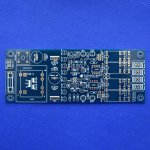
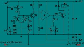
DC is detected thru R7, D2 should detect +DCV and D1 should detect -DCV. C2 and C3 shunt all but the lowest frequencies and DC to ground. Ground connection is clearly there.
Craig
Craig

And if you are worried about introducing ground loops the GND for the board can be tied to the amp’s GND thru a 10-ish ohm resistor. Assuming that R7 is much larger, but my guess is its at least a few k.
Thanks guys, yes r7 is 22k , but if you look at the picture, the board has it's own transformer and regulation, and there is absolutely no connector for amp ground.
A novice like myself could assemble the board, observe that relays are triggered at delay, and think, this thing works, but it doesn't, no protection from dc, unless you make your own gnd to gnd.
I wonder how many amps this thing sits in, and doing nothing else but delay speakers.
A novice like myself could assemble the board, observe that relays are triggered at delay, and think, this thing works, but it doesn't, no protection from dc, unless you make your own gnd to gnd.
I wonder how many amps this thing sits in, and doing nothing else but delay speakers.
You can test DC detect by connecting a simple 1.5V AA or AAA battery between 'IN' and 'GND'. Invert the battery and repeat the test.
I could do that, and will later, my point is that this board, WILL not work..! If connected as it is.. and there's probably sold hundreds of them, did everybody discover the missing amp ground..? I think not.
The ground should be almost everywhere and easily recognizable around your pcb.
Drill a couple of holes 5mm apart, insert and solder a faston et voilà, GND.
Drill a couple of holes 5mm apart, insert and solder a faston et voilà, GND.
I know I know.... my point is still this board is sold with a missing ground connector, i paid for a working board, not one that needs tweaking for working...
And my point number 2. This board could be installed in several amplifiers, and the owner thinks his 10000 dollar speakers are safe, they're not..!
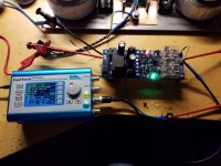
Got a look at and board just now, with the new ground wire, I can trigger the relays with my signal generator, triggers at an offset of 1.5 volts, so it works, I'm happy..
Tried working down on low hz, 2hz no trigger, 1hz , red and green light show
Tried working down on low hz, 2hz no trigger, 1hz , red and green light show
Attachments
I could be wrong, maybe the board not include ground connector is to avoid damage if someone connect it to a BTL amp.
Why it has two relay per channel? can you provide a link to the selling site?
Why it has two relay per channel? can you provide a link to the selling site?
Hi Chris.
It is strange, I have asked the dealer what's going on with his board, but I have got nothing but silence, relays are paired in parallel, for less resistance and durability I guess
Here's the link.
https://www.hifistor.com/index.php/product/hifi-professional-audio-speaker-protection/
It is strange, I have asked the dealer what's going on with his board, but I have got nothing but silence, relays are paired in parallel, for less resistance and durability I guess
Here's the link.
https://www.hifistor.com/index.php/product/hifi-professional-audio-speaker-protection/
As voltage is defined as a potential w.r.t. another one, your circuitry/PCB of course needs to be grounded. In your specific case, tie it's GND terminal to chassis GND, as the current flow through both R7's is minuscule.
Best regards!
Best regards!
Hello.
Yes it is mounted in chassis now and taking ground from the two 10r resistors ( one for each psu ground )
Its tested and functioning.
But I ask myself why didn't they put a ground pin to the pcb in first place, can see they sold some more than a few, and I bet it is installed in some amps without ground, and only working as delay, removing pop starts
The answer is Negligence. Period.But I ask myself why didn't they put a ground pin to the pcb in first place,
I've seen, and bought, a headphone amp board that missed a filtering capacitor after the bridge rectifier for its auxiliary power supply, and the ripple current went all the way to the far side of a three-terminal regulator, sharing a return path on the PCB with the headphone output return Ground, back-driving a 120Hz hum into the phones directly, laud and clear!
Supposedly that's why they badged it »Profesional« 😗...
The missing ground terminal corresponds to the lacking »s«.
Best regards!
The missing ground terminal corresponds to the lacking »s«.
Best regards!
- Home
- Amplifiers
- Solid State
- Loudspeaker protection flawed design?