I'm getting there, however on the bulwark input card or any card for that matter: I see the layout for the BJT. It has a double line on the silkscreen. I assume this is the back of the transistor. The front has the nomenclature? Q 2,5 and are shown.
Attachments
The double line on the silkscreen stands for the back of the transistor package.
It represents the built in heatsink on some packages, or the side where a separate heatsink would be attached.
It represents the built in heatsink on some packages, or the side where a separate heatsink would be attached.
You received some useful advice in the other thread
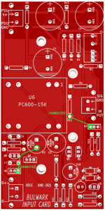
Or as we say in the electronics lab, "when in doubt, buzz it out". The verb buzz means "use the continuity test feature of a digital multimeter"; when there is continuity between the probes, your DMM makes a buzzing / beeping sound.
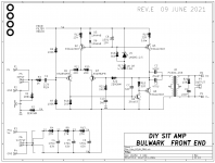
There are only three BJTs with rectangular footprints on the Bulwark PCB, so this won't take a long time. As a double-check / verification of your continuity testing work, I've marked a couple of pairs-of-pins which should show connectivity using your buzzer. This will give you confidence that you're doing everything correctly. After you know what's connected to what, consult the schematic! Presto, the identification is complete.
Naturally it's best to buzz out pins on either end of the transistor package; if you buzz the one in the middle, it can't tell you the correct orientation, since middle = middle whether you rotate the package 180 degrees, or zero degrees.
_
... To solve that riddle, I identified the three pins on the transistor in question, and then consulting the schematic and the trace lines on the board determined how the transistor pins were oriented on the board.
Or as we say in the electronics lab, "when in doubt, buzz it out". The verb buzz means "use the continuity test feature of a digital multimeter"; when there is continuity between the probes, your DMM makes a buzzing / beeping sound.
There are only three BJTs with rectangular footprints on the Bulwark PCB, so this won't take a long time. As a double-check / verification of your continuity testing work, I've marked a couple of pairs-of-pins which should show connectivity using your buzzer. This will give you confidence that you're doing everything correctly. After you know what's connected to what, consult the schematic! Presto, the identification is complete.
Naturally it's best to buzz out pins on either end of the transistor package; if you buzz the one in the middle, it can't tell you the correct orientation, since middle = middle whether you rotate the package 180 degrees, or zero degrees.
_