I recently shipped an ancient Threshold FET 10/pc preamp to my son. It was working last time I used it but one channel was DOA when it arrived. I have the unit back and am contemplating a repair strategy. Given that the unit is at least 30 years old I'm thinking beyond just hunting down a bad semiconductor or whatever. Bad solder joint from rough shipping? A bad electrolytic? Combination of things or cascade of failures? Regardless, I want to get it fixed for another 30 years.
Thus far I have located the point on the board where the input signal goes dead. Power supply works fine and no sign or anything burnt. So, what I have in mind is:
Thus far I have located the point on the board where the input signal goes dead. Power supply works fine and no sign or anything burnt. So, what I have in mind is:
- recap everything and reflow all the joints on the board on principal (eliminate those potential sources of failure and reduce liklihood of future failure)
- diagnose what's actually blown and replace accordingly if the above doesn't fix it.
A recap is benefical. But rarely a capacitor causes the amp to mute completely. So imo you nedd to replace the caps checking that the good chanel remains OK. Change 3 or 4 units and test. If OK, continue. If something went wrong, the problem is circumscript to last changes only. Thus with one ch at full performance, you can compare the DC and AC voltages accelerating rhe troubleshooting time.
Can you supply pictures of the pcb, both sides? Just to give the audience an idea.
And an indication where the show stops.
If larger parts like caps are not fixed to the pcb/otherwise, vibration can do harm to the legs. Maybe even broken during transport indeed.
tiefbassuebertr gives a overview of all Thresholds ( FET-10Pc Stereo Phone Gain Stage (1986-89 under Stereo Line + RIAA Preamplifier):
https://www.diyaudio.com/community/...nd-schematic-collection-of-all-models.175138/
And here:
https://6streetbridge.blogspot.com/2009/05/visit-with-threshold-fet-10pc-phono.html
Do not replace any film capacitors at all. They will not require it.
In fact, you should do nothing (including soldering) until you get
a schematic diagram, and troubleshoot the actual problem with
your test equipment. Do not attempt to fix this by just replacing parts.
That is a very bad strategy, and is likely to cause more trouble instead.
If necessary, reverse engineer a schematic first.
Last edited:

Thanks for the remarks, very helpful. Unfortunately the FET 10/pc wasn't included in any of the schematics so I'll have try to do without. In any case, the PC board is shown below. The bottom section in the box seems to just be PS regulation. The respective channels are more-or-less mirror images of each other. I labeled the last signal transistors as R1, R2, L2 and L1. IOW, R1 and L1 occupy the same positions in the signal path for respective channels. Likewise R2 and L2.
Here's what I did: Fed a 3mv 1200hz signal to the inputs. I used a scope to trace the signal forwards from the input to the output to see where the trouble starts. The problem area is shown in the detail, specifically L1. The PC trace on the left is 18v going to the far left conductor on L1 (PN4250a). The center conductor shows the signal just fine, corresponding to R1. The rightmost conductor should show the same signal per R1. Instead it's a kind of bizzare, high level noise. The signals on L2 (MPSA92) correspond perfectly with its fellow, R2. Anyway, the signal (greatly reduced) goes into the green cap. This seems to be a kind of coupling cap (???) in series with the output jack. The output side of that cap is zero. Can it be open? Also, I removed (and reinstalled) L1 to try to test it with an ohmmeter but it seemed ok. That's also what made the rosin mess.
So, it's looking to me that the likely problem is L1 even though it "tested" ok. To move things along I ordered the electrolytics, L1 and L2 from Mouser. Very cheap, so why not? Hope this is all clear. I'm a beginner at this stuff so my nomenclature etc is probably wrong. Thanks for the suggestions so far. Cheers,
If there is signal at one end of a coupling capacitor, but no signal at the other end,
that is bad and should be checked into further. Easiest would be to bridge temporarily
another cap across it to see if you now get signal. However, if the no signal end was
grounded by a circuit fault, that test would fail.
that is bad and should be checked into further. Easiest would be to bridge temporarily
another cap across it to see if you now get signal. However, if the no signal end was
grounded by a circuit fault, that test would fail.
L1 and L2 are both PNP transistors. MPSA92 pinning is EBC (flat face front), PN4250A unknown.The problem area is shown in the detail, specifically L1. The PC trace on the left is 18v going to the far left conductor on L1 (PN4250a). The center conductor shows the signal just fine, corresponding to R1. The rightmost conductor should show the same signal per R1. Instead it's a kind of bizzare, high level noise. The signals on L2 (MPSA92) correspond perfectly with its fellow, R2. Anyway, the signal (greatly reduced) goes into the green cap. This seems to be a kind of coupling cap (???) in series with the output jack. The output side of that cap is zero. Can it be open? Also, I removed (and reinstalled) L1 to try to test it with an ohmmeter but it seemed ok. That's also what made the rosin mess.
Check if the signal is present on the middle pin of L1, that should be the input (base).
If the left pin is on 18Vdc supply, the right pin should be the output... but there is noise.
How about R1? Is on the same 'right' pin, caseview-spoken, signal present?
If so, L1 is broken (or shorten, or something).
Check L1 again but with a diode tester.
You can clean the pcb with IPA.
This is great, many thanks to all. A little more testing indicated that the 10uf coupling cap is open. Unexpected I guess but certainly not impossible. It also looks like L1 is actually ok. Either it miraculously healed itself or I didn't penetrate the pc board enough to make good contact. Whatever, the signal is the same on b oth sides up to the output coupling caps. A replacement is on order, as well as a handful of the transistors in case those end up being needed.
So the next question: Let's assume that replacing the coupling cap fixes things. Would it be good to replace the cap on the other channel just to keep things the same? Same goes for semiconductors. If L1 is bad should it's counterpart L2 be replaced? And does this extend to the other channel? Seems like doing so would be the most "symmetrical." Does that matter or would it be best practice? Cheers,
So the next question: Let's assume that replacing the coupling cap fixes things. Would it be good to replace the cap on the other channel just to keep things the same? Same goes for semiconductors. If L1 is bad should it's counterpart L2 be replaced? And does this extend to the other channel? Seems like doing so would be the most "symmetrical." Does that matter or would it be best practice? Cheers,
Most likely....or I didn't penetrate the pc board enough to make good contact...
...Would it be good to replace the cap on the other channel just to keep things the same?...
Depends on the replacement cap. If excatly the same: no. Else: your choise.
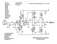
Thanks, some similarities but not the same. Mine is FET 10/pc.schematic:
- Home
- Source & Line
- Analog Line Level
- Ideas on old preamp repair