Have read up on replacing the electrolytics when out of spec BUT.. does replacing the original green caps for the tweeter section result in a noticeable improvement with say Ansar Supersound or other new polys?
If in they're in spec, keep the greens or change?
The boards were recapped about 5 years ago and as one can see, it's nearly all ALCAPS which is generally seen as a good thing I believe.
Any advice appreciated.
If in they're in spec, keep the greens or change?
The boards were recapped about 5 years ago and as one can see, it's nearly all ALCAPS which is generally seen as a good thing I believe.
Any advice appreciated.
Attachments
Can you identify any part markings on the green capacitors it may give a clue as to their composition. I remember caps of that type, but I cannot recall if they were mylar or polystyrene types. Manufacturer Erie or Phillips, if they are a plastic composition they shouldn't have degraded. Unless they have age related reliability issues, don't we all.
A more modern capacitor could be a smidge better, but if they still measure up to the spec, I would leave them alone
A more modern capacitor could be a smidge better, but if they still measure up to the spec, I would leave them alone
Thanks Raymondj.
The most easily visible green cap's part marking reads: 'ERIE 1.5uF / 250V Type M312'
About to take some measurements. Ok to test a caps on the board if only one connection is lifted, or does that only apply to diodes and resistors.?
Any tips on testing the components on the board? I only have a DMM and a cheap transistor tester which also measures caps.
Sorry only just seen this.
As the caps look like they are all wired in parallel lifting one end will allow you to take the capacitance of that branch, i.e all of them together if there are four you should have approx 6 uF on your meter. A reading of 5.4 to 6.6 reading indicates they are still good from a capacitance point of view..
If you want like for like replacement some are available on ebay.uk
Thanks.
Well after 50 years these green caps are still very close to spec. Thinking that maybe I should just leave them be as they seem very much at home. Would be good to hear if anyone experienced a really substantial improvement by replacing with good quality polys.
Ansar Supersounds are often recommended but I don’t think the correct sizes are currently available.
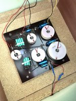
With reference to the pic below with labels..
The two 72uF’s are reading 75uF and 76uF. What discernible effect, if any, should this have? Just leave in place?
The Alcap reading 4.35 uF should be 4 uF. Fine to leave in place?
The 29uF Alcap is often replaced with Mundorf E Plain caps. Would like to ‘upgrade’ but many users also describe some audio issues even with the addition of another cap or resistor to compensate for changes in ESR?

Well after 50 years these green caps are still very close to spec. Thinking that maybe I should just leave them be as they seem very much at home. Would be good to hear if anyone experienced a really substantial improvement by replacing with good quality polys.
Ansar Supersounds are often recommended but I don’t think the correct sizes are currently available.
With reference to the pic below with labels..
The two 72uF’s are reading 75uF and 76uF. What discernible effect, if any, should this have? Just leave in place?
The Alcap reading 4.35 uF should be 4 uF. Fine to leave in place?
The 29uF Alcap is often replaced with Mundorf E Plain caps. Would like to ‘upgrade’ but many users also describe some audio issues even with the addition of another cap or resistor to compensate for changes in ESR?
Also, does anyone know whether Celestion kept the inductors to the same spec whether they fitted MD500's or MF500's?
I would turn at least 2 of those air core coils at right angles (on end) or place the biggest ones in the corners
I would be surprised if this was their actual stock layout ?
I would be surprised if this was their actual stock layout ?
The suggestion for turning the air-cored inductor coils so that they are at right angles to each other is a good one. The present layout does seem to be a good candidate for mutual coupling effects to occur between the inductors. It would be interesting to see measurements of what these might be, but that's probably not an entirely easy thing to do.
As for the effects of variations in the values of the capacitors from their printed component values, that can be hard to predict. They all seem to be within 10% or so of their stated values, which is probably within their original tolerance range. To get an idea of the potential effects of component variations, it would be useful to create a simulation of the crossover network using Xsim or VituixCAD. That way you could see what frequency ranges are affected when you change the values of the various capacitors, as well as the +/- dB changes that result.

Replace the electrolytics without question,
If the greencaps are OK (including ESR measurements), leave them, would it cost that much to try newer caps?
re:'turning the air-cored inductor coils' - the counter argument to this is -'that's how they were originally voiced, leave them as is'
One step at a time
This guy may be able to help, he has experience with Dittons:
https://www.youtube.com/channel/UC_sacPWzRAWVyG5xOkx0Eeg/videos
Re:'recapped about 5 years ago" - missed this bit, the electros seem to be within tolerance, so probably OK for now
Thanks guys, all of this advice very much appreciated.
Almost certain that this is the stock layout for the inductors.
Am going to reduce the 36uF to 29uF utilising the now unobtainium Alcap currently in situ.
Will double check and improve gaskets on the speaker cut outs and see how it sounds with all this done. Then take it from there. Naturally, will have to inspect the other speaker and duplicate where necessary.
@cb1 I've used VituixCAD to create a circuit model as per the crossover circuit diagram and parts list provided above. The woofer, midrange and tweeter are all assumed to have an 8-ohm constant resistance as their impedance. All of the inductors also include some series DCR to account for the DC resistance of the wire in the inductor coils.
The crossover circuit model looks like the following. Please check it to see if it's 100% correct.

The above crossover circuit model produces the following filter transfer functions:

The crossover circuit model looks like the following. Please check it to see if it's 100% correct.
The above crossover circuit model produces the following filter transfer functions:
Last edited:
A Ditton 66 crossover board whose components have been measured can be found here: https://www.jkwynn.co.uk/66_HTML/66_11.html
@witwald thank you very much for this incredibly helpful contribution. Many Celestion Ditton 66 owners and restorers the world over will be able to benefit from your work at some point in time.
If you should happen to have an idle moment… I’d be very interested to see how my own circuit board’s graph is affected given its slight variations in capacitor values. For other users such a calculation would allow them to know the degree to which slight variations affect (or perhaps hardly affect?) the crossover graph.
Apart from the capacitors, everything else is the same as your original calculation based on the stock data sheet. Both my left and right speaker's crossover components readings are very very similar.
C1 - 75.15uF
C2 - 76.16uF
C3 - 4.354uF
C4 - O uF capacitor is removed (C4 and C5 are in parallel)
C5 - 29.00uF
C6 - 1.497uF
C7 - 1.497uF
C8 - 1.497uF
C9 - 1.497uF
C10 - 1.306uF
C11 - 1.306uF
C12 - 1.306uF
I've modified the circuit model to match your capacitor component values and the removal of C4. The new circuit diagram is shown below:

The filter voltage responses that it produces are shown below:

The above circuit model includes the measured results for inductor DCR obtained by J. K. Wynn, who tested a Ditton 66 crossover network (https://www.jkwynn.co.uk/66_HTML/66_11.html).
After revising my circuit model to accommodate the as-tested DCR values, the component values based on the stock data sheet are as shown below:

The above circuit produces the following filter voltage responses, which are different from the previous set, but in very, very subtle ways:

The filter voltage responses that it produces are shown below:
The above circuit model includes the measured results for inductor DCR obtained by J. K. Wynn, who tested a Ditton 66 crossover network (https://www.jkwynn.co.uk/66_HTML/66_11.html).
After revising my circuit model to accommodate the as-tested DCR values, the component values based on the stock data sheet are as shown below:
The above circuit produces the following filter voltage responses, which are different from the previous set, but in very, very subtle ways:
Thank you. How special to have a custom reading!
Does it look like a good one to you or are there any flaws that are concerning?
Also, I measured my drive units' resistances whilst disconnected and they were:
Tweeter: 4.5 ohms
Midrange: 6.5 ohms
Bass: 4.5 ohms
Would this affect the chart much?
Does it look like a good one to you or are there any flaws that are concerning?
Also, I measured my drive units' resistances whilst disconnected and they were:
Tweeter: 4.5 ohms
Midrange: 6.5 ohms
Bass: 4.5 ohms
Would this affect the chart much?
You're welcome. I'm happy to help out. I've changed the bass, midrange and tweeter voice-coil resistances to your values. This does cause a large change, and the filtered responses are now as shown below:

It is apparent that reducing the values of each of the driver voice-coil resistances has had a large effect on the shapes of the filters in their transition bands. I would tend to say that the filter responses now look a bit more like what I would expect.
Of course, using a constant voice-coil resistance in the circuit simulations does introduce a high degree of uncertainty into the simulations. Still, I think the plots do provide some useful information related to the general design behavior of the crossover network.
One of the interesting things that the simulation shows quite clearly, is that there is a bit of attenuation of the woofer's response in the 10–100 Hz region. This is due to the combined DCR of the two inductors in series with the woofer's 4.5-ohm voice coil, which results in 3.3 dB of loss. I expect that the woofer would have had a quite high sensitivity, what with its 4.5-ohm value of Rvc. This meant that the midrange and tweeter didn't need their output to be attenuated by the filter, hence the absence of resistors.
It's also apparent that the midrange is boosted by about 0.8 dB. Whether or not this occurs in practice once a real midrange driver is connected, I just don't know. At present, it shows that there is a resonant circuit being created, which is what leads to the slightly boosted output in the midrange's passband.
- Home
- Loudspeakers
- Multi-Way
- Celestion Ditton 66 crossover original green film caps - keep or replace?