I am a newbie, so my apologies if anything is wrong with my question. I am building a +/-18V 0.3A power supply for my phono preamp. The supply is fed by 4 LiFePO4 batteries (2+2). When fully charged, each battery is close to 13.5V, so the maximum input voltage is +/-27V. When any battery is drained to 10V, it shuts itself off completely. This would make the input voltage drop on one side with unpredictable and potentially dangerous outcomes. I'd like to use a simple protection circuit to shut off the input voltage completely when any of 4 batteries approaches the 10V threshold. I have no experience with such circuits, so here is just my intuitive wish list:
1. 4 sensors, each monitoring the voltage of one battery (perhaps based on a voltage reference driving an opamp?)
2. A relay with mechanical (or hercon) contacts. The relay feeds itself - once disconnected, it cannot reconnect without me pushing the start button.
3. One relay disconnects both +27 and -27 inputs (or whatever the voltage is by then) - disconnects all batteries from the power supply - as soon as any one of the 4 sensors is triggered by the voltage of any battery dropping below a chosen threshold.
4. Ideally a LED turning on or off as an indicator that the protection has triggered.
I would appreciate any thoughts, links, schematics, parts suggestions, etc. Thank you for your help and expertise!
- Alex
The easiest way imo is a window comparator. I made several years ago a battery regulator for my solar energy power system, and logic shuts down the fan and the power stage when cell voltage is insufficient; during night or cloudy days. A window comparator with TS3702 (CMOS LM393 with internal pullup) trigerring a sr flip flop 4011 does it job from more than 12 years ago every day.
Window comparator has the great advantage that you can set independently the on and off levels or theresholds. You can do it for the full battery voltage or indepently for each arm or cell and ORed toguether trigger the shutdown mechanism.
Window comparator has the great advantage that you can set independently the on and off levels or theresholds. You can do it for the full battery voltage or indepently for each arm or cell and ORed toguether trigger the shutdown mechanism.
Attachments


+/-18V 0.3A power supply for my phono preamp.
IMHO, that's a big phono preamp. We didn't use that much even in broadcast when driving long lines and through patchbays and multiples.
However you are right about loss of one rail and incompletely analyzed circuits.
Might it be simpler to build one-rail with a rail-splitter? This whole "+/-" thing is about flat-to-DC response, what we DON'T want in audio. Coupling caps harm sound much less than pickup coils burned-open in a supply collapse. KISS, lesser of available evils, etc.
Use four open collector comparators, with the outputs all connected together to one pull up load resistor to Vcc.
It's like a 4 input NAND circuit. Then when any one input voltage is too low, the comparator output node will go low.
Then do what you need with that information. Hysteresis is necessary when using comparators, to avoid chatter.
The LM339 is a quad comparator, and the LM393 is a better, dual comparator.
Last edited by a moderator:
Use four open collector comparators...
Sounds great, thanks! Is there any chance you could provide some basic schematics (even if hand drawn) or share a link to where this is explained in more details, as I lack the expertise to design this from scratch myself even if based on a great idea. Thanks again!
Well, it's a little harder than that, since you want to use bipolar supplies.
Maybe after some thought.
In the same chassis, is there a constant voltage available from a line operated supply?
That might be needed for the control.
Maybe after some thought.
In the same chassis, is there a constant voltage available from a line operated supply?
That might be needed for the control.
In the same chassis, is there a constant voltage available from a line operated supply?
No, it is just 4 batteries. However, the idea is not to wait for a battery to shut itself off (which happens at 10V), but to shut down the whole thing when any of the batteries reaches 11V and is still working. Therefore a relatively constant voltage of 11-13.5V is always available from any battery.
Instead of hysteresis, I am thinking of a latching relay circuit - once the protection triggers, a manual reset is required.
Window comparator has the great advantage that you can set independently the on and off levels or theresholds. You can do it for the full battery voltage or indepently for each arm or cell and ORed toguether trigger the shutdown mechanism.
Thanks for your insight! What do 4011 drive that turns off the power circuit? And how can they be OR-ed together in a bipolar circuit? Also, how do I shut down both arms when the voltage gets low only in one arm? Thanks again!
Might it be simpler to build one-rail with a rail-splitter?
One rail would take higher voltage caps and higher power resistors that would not fit on the existing board...
My solar cell regulator is made with two buck converters running 100KHz, its outputs paralleled but 180° out of phase. The oscillator a HCF4047 generates 200KHz square wave at pin 13 and from pin 10 and 11 I took the opposit polarities pulses to trigger TS556 dual CMOS 555 (monostable PWM genny) AC coupled and from 556 outputs, a chain of drivers to reach the IRF540 power MOSFET's. The output of the HCF4011 Flip Flop enables or disables 4047 oscillator, thus all the PWM chain stops when no pulses are generated.
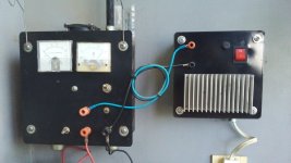
There is a fan in the top of the box that runs pwm controlled speed from a diode sited on 540's heat sinks. When logic is off, the fan is also disabled. This pic is off date, but suffices to see the internal construction.
There is a fan in the top of the box that runs pwm controlled speed from a diode sited on 540's heat sinks. When logic is off, the fan is also disabled. This pic is off date, but suffices to see the internal construction.
Attachments

How do you recharge the batteries, take them out, or plug in a charging circuit to the battereis?No, it is just 4 batteries. However, the idea is not to wait for a battery to shut itself off (which happens at 10V), but to shut down the whole thing when any of the batteries reaches 11V and is still working. Therefore a relatively constant voltage of 11-13.5V is always available from any battery.
On Mouser, look under the menu:
All Products-Semiconductors-Integrated Circuits - ICs-Power Management ICs-Supervisory Circuits
Any number of these can be used to trigger a reset to disable the power and restore when back within limits. Would need to divide voltages down for your application, of course.
Hal
All Products-Semiconductors-Integrated Circuits - ICs-Power Management ICs-Supervisory Circuits
Any number of these can be used to trigger a reset to disable the power and restore when back within limits. Would need to divide voltages down for your application, of course.
Hal
The batteries will need to be charged only once a month or two. So the idea is to have a single On/Charge manual switch. In the On position, all batteries are connected to and feed the power supply, but are disconnected from the chargers. In the Charge position, it is the opposite.How do you recharge the batteries, take them out, or plug in a charging circuit to the battereis?
Great work, thanks for the details! Can 4011 directly control power MOSFET's to disconnect the batteries in my case? If so, what MOSFET parameters should I select? I would want a low on-resistance, but not huge powerful units.The output of the HCF4011 Flip Flop enables or disables 4047 oscillator, thus all the PWM chain stops when no pulses are generated.
This is helpful, thank you!All Products-Semiconductors-Integrated Circuits - ICs-Power Management ICs-Supervisory Circuits
CMOS gates can drive MOSFET's very well provided frequency isn't too high, say, 10KHz directly. No need for voltage dividers. Perhaps a 47R in series to reduce ringing. 74HC and 74HCT series are better as they have larger current capacity. Also HCF4049 and 4050.
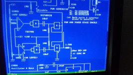
This is my schematic done with ASCII art in my 486 DOS pc. This is the part I mentioned above regarding charger enable/disable.
This is my schematic done with ASCII art in my 486 DOS pc. This is the part I mentioned above regarding charger enable/disable.
Attachments
- Home
- Amplifiers
- Power Supplies
- Undervoltage protection and shut off schematics