Hello all
By chance does anyone have a picture reference or a BOM for the aux power supply area of the Orion HCCA 4500.1D SPLX?
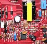
As you can see there was a heatsink short to the resistors. I think the Isense resistor is incorrect as I had to guess at a value.
Thank you all

By chance does anyone have a picture reference or a BOM for the aux power supply area of the Orion HCCA 4500.1D SPLX?
As you can see there was a heatsink short to the resistors. I think the Isense resistor is incorrect as I had to guess at a value.
Thank you all
Thank you, Perry and I hope all is well.
One of the 2.7-ohm resistors was still legible so since they were in parallel I figured they would be the same. The Isense resistor and pull-down resistors value I have installed may be the problem.
One of the 2.7-ohm resistors was still legible so since they were in parallel I figured they would be the same. The Isense resistor and pull-down resistors value I have installed may be the problem.
Last edited:
Hi Perry
The designator is no longer present but it is R29 (470-ohms) in your picture that I do believe goes to pin 3 of IC. I am having a hard time finding this issue. 50% duty cycle at 5khz. It will not charge C593, C594, or C597-C600 acting as if the load is too high but there are no shorts on the VA lines. I can lift R597 and R598, the 4.7-ohm resistors for VA+ and VA- which allows C591 and C592 to charge VERY slowly over many many seconds to 15 volts positive and 17 volts negative.
The original fault was a piece of loose conductive material shorting the Q584 drain heatsink to one side of R593a as noted in the picture. I did have to repair one of the transformer windings right at the post (pin 3) and shows no other open windings.
I am not sure that 5khz is correct on the switching frequency.
The oscillating frequency is likely going to be about 50kHz.
The pulldown resistor between the gate and source of the FET should be 47k, not 47 ohms.
The resistor between Isense (pin 3 on the IC) and the source of the FET should be 470 ohms.
The pulldown resistor between the gate and source of the FET should be 47k, not 47 ohms.
The resistor between Isense (pin 3 on the IC) and the source of the FET should be 470 ohms.
Thank you for your time, Perry,
I changed the resistors to the values they were supposed to be as soon as you posted the picture. I have found that the transformer still has an internal short on the primary as it shows zero inductance at 2 ohms at each end to the center tap.
Do you know of a link or source to a replacement transformer with these specifications?
I don't have a source but I think the following amps use this circuit.
Hertz MP15k
PPI PDX-10k
Have you tried removing the yellow tape to see if you could see a damaged area or possibly to see if the primary was on the outside of the windings so it could be rewound?
Hertz MP15k
PPI PDX-10k
Have you tried removing the yellow tape to see if you could see a damaged area or possibly to see if the primary was on the outside of the windings so it could be rewound?
Thank you Perry for help on this. I did unwind the transformer and sure enough, the very last set of windings, which is the primary side, melted and shorted. I do have the wire and I will be re-winding the transformer.
I just noticed that the signature line no longer exists. It has been a while since I was last in.
I use two different supplies depending on the amplifier on the bench a 2A and a 10A brick for initial testing.
Thank you Perry and I hope all is well.
I use two different supplies depending on the amplifier on the bench a 2A and a 10A brick for initial testing.
Thank you Perry and I hope all is well.
The signature is available to people who pay to support the site and is only visible to others who also support the site.
- Home
- General Interest
- Car Audio
- Orion HCCA4500.1D SPLX - 2021A Aux. Power Supply Area Parts Identification