Hello everyone!
I'm an electronical enthusiast and beginer in this beauty world!
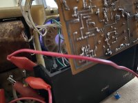
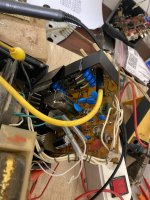
I have an URSS oscilloscope that it's broken and from a while I try to fix it.
The main problem it's in the high voltage power supply, another problem it's my lack of knowledge about CRT and how they work.
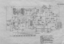
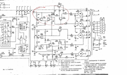
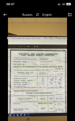
I found the data sheet for this CRT valve but I can't understand what it's the pin no. 2 on and what this is doing. First I try to repair the original power supply which is made with an iron powder transformer and self-oscilation circuit but this doesn't work properly and I couldn't make this supply to work properly.
Now i try to make another type of power supply that it's based on push-pull topology and another core ( ETD34 ) at 30kHz. unfortunately I didn't had time to experimented with this new supply.
What I want to understand it's what does every plate in this tube and how it works. I want to check all the supply voltages without the tube connected (with some load resistors) to be sure that everything it's fine.
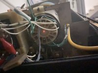
I didn't saw this CRT at work, I received the osciloscope ( C1-118A URSS model) few months ago as a "gift"and broken, but as I knew the device worked in the past, now the tube seems to have some good signes, the filament it's glowing, and also I don't know why this appear and also if it's bad or not for the tube itself.
For sure the tube doesn't accelerate. Maybe with the new transformer the tube will work without any problem, anyway I want to learn from you and hear your opinions!
I'm looking forward for your answer and I really want to learn more about CRT and electronics.
Thank you in advanced!
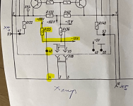
I know that on:
pin 1 and 14 it's the heater lamp (also this it's checked and it seems to be ok )
pin 2 it's a mistery (this pin it's connected via an potentiometer between -12V and +100Vcc), maybe with this pot can I adjust some geometrical issues?
pin 3 it's the cathode
pin 4 it's the gride
pin 5 it's the 4th anode
pin 6,9,11 not used
pin 7,8 X (time base ) plates
pin 10 astigmatism
pin 12 focus
pin 13 2nd anode accelerating
D1,D2 Y plates
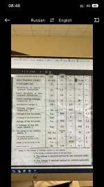
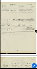
http://lampes-et-tubes.info/cr/11LO9I.pdf
11LO9I (11ЛО9И) Oscilloscope CRT
For more photos I leave below links:

I'm an electronical enthusiast and beginer in this beauty world!
I have an URSS oscilloscope that it's broken and from a while I try to fix it.
The main problem it's in the high voltage power supply, another problem it's my lack of knowledge about CRT and how they work.
I found the data sheet for this CRT valve but I can't understand what it's the pin no. 2 on and what this is doing. First I try to repair the original power supply which is made with an iron powder transformer and self-oscilation circuit but this doesn't work properly and I couldn't make this supply to work properly.
Now i try to make another type of power supply that it's based on push-pull topology and another core ( ETD34 ) at 30kHz. unfortunately I didn't had time to experimented with this new supply.
What I want to understand it's what does every plate in this tube and how it works. I want to check all the supply voltages without the tube connected (with some load resistors) to be sure that everything it's fine.
I didn't saw this CRT at work, I received the osciloscope ( C1-118A URSS model) few months ago as a "gift"and broken, but as I knew the device worked in the past, now the tube seems to have some good signes, the filament it's glowing, and also I don't know why this appear and also if it's bad or not for the tube itself.
For sure the tube doesn't accelerate. Maybe with the new transformer the tube will work without any problem, anyway I want to learn from you and hear your opinions!
I'm looking forward for your answer and I really want to learn more about CRT and electronics.
Thank you in advanced!
I know that on:
pin 1 and 14 it's the heater lamp (also this it's checked and it seems to be ok )
pin 2 it's a mistery (this pin it's connected via an potentiometer between -12V and +100Vcc), maybe with this pot can I adjust some geometrical issues?
pin 3 it's the cathode
pin 4 it's the gride
pin 5 it's the 4th anode
pin 6,9,11 not used
pin 7,8 X (time base ) plates
pin 10 astigmatism
pin 12 focus
pin 13 2nd anode accelerating
D1,D2 Y plates
http://lampes-et-tubes.info/cr/11LO9I.pdf
11LO9I (11ЛО9И) Oscilloscope CRT
For more photos I leave below links:
Attachments
-
 rsz_a465d08a-f33d-455e-88d8-af89f0ada81d.thumb.jpg.4c50dabecffe5515d958dfedce78f6f5.jpg137.8 KB · Views: 94
 -
 post-143521-0-37826900-1418495860.jpg517.5 KB · Views: 87
 -
 FF178B59-563E-4847-802C-7D4B4B06CA0F.png871.8 KB · Views: 87
 -
 F8A770D0-A3C4-4AE5-A0C3-F13E486AB097.png732.9 KB · Views: 97
 -
 E872A271-5A40-4C1A-A8C8-C51941635072.jpeg347.9 KB · Views: 93
 -
 D0A0C9D9-4DF5-4434-9330-C4193DB9E51F.jpeg456 KB · Views: 110
 -
 A274CC03-F883-4CC2-BFA2-990DE6D768D4.thumb.jpeg.7aeeaaa084f33d1b036cea906ba72f1c.jpeg353 KB · Views: 93
 -
 8450A7D2-1C07-490D-94BC-5393F6E74607.png917.9 KB · Views: 102
 -
 021F8593-496B-4891-A822-A34DE3BF9FF7.png1.2 MB · Views: 87
 -
 08DEA48E-FB5D-4334-B371-F4846E4450AA.thumb.jpeg.cd6af0d6d1dc5c2cd6b137a56a51b781.jpeg245.6 KB · Views: 93
 -
 post-143521-0-33481000-1418495676.jpg569.5 KB · Views: 112
Last edited: