It's well known that using an ideal inductor for Le typically gives wildly inaccurate results at high frequencies. In a past project, I used two inductors in series plus parallel resistors to get the impedance to track better. Recently, though, I was wondering whether an intentionally 'bad' inductor with a solid low-carbon steel core could work instead, given that that's basically what's in most guitar speakers. Thoughts?
You mean in a spice simulator? It's basically a transformer where the conductive core doubles as a short-circuited secondary coil. Then there's the signal-dependent variable air gap among other things.
The difficult I see that the resistive part of the inductor will be difficult to keep under control. But the basic idea is good.
Thanks for the replies. I'll probably eventually build and measure what I proposed to see if I get something usable. Just wondering whether someone here had tried something similar before.
What about an iron powder core? As long as you could get the flux density high enough, it seems like it could be superior to the widely used conductive cores. The electrical component of Qms would have less damping, so there would also be less variability as the VC moves around.
I think you've misunderstood my original question. The goal is to build a dummy load with an impedance curve that closely follows that of an existing speaker.
Loudspeakers usually exhibit what is often called semi-inductance. In other words, the voice coil inductance decreases as frequency increases. Most inductors on the market endeavor to minimize this non-ideal characteristic so that they behave more like ideal inductors over a wide frequency range.
Here's an example of a simple loudspeaker equivalent circuit (loosely based on the Eminence Private Jack):

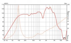
If Le is a constant inductance, the resulting impedance curve has the wrong shape above ~500Hz. The measured impedance of the real speaker shows that the inductance at 20kHz is about half of the value around 2-3kHz:

It's possible to get this decreasing inductance characteristic by stringing multiple near-ideal inductors together with parallel resistors, but I was thinking that another option might be an inductor with a solid low carbon steel core (rather than the typical laminated or powdered core).
Loudspeakers usually exhibit what is often called semi-inductance. In other words, the voice coil inductance decreases as frequency increases. Most inductors on the market endeavor to minimize this non-ideal characteristic so that they behave more like ideal inductors over a wide frequency range.
Here's an example of a simple loudspeaker equivalent circuit (loosely based on the Eminence Private Jack):
If Le is a constant inductance, the resulting impedance curve has the wrong shape above ~500Hz. The measured impedance of the real speaker shows that the inductance at 20kHz is about half of the value around 2-3kHz:

It's possible to get this decreasing inductance characteristic by stringing multiple near-ideal inductors together with parallel resistors, but I was thinking that another option might be an inductor with a solid low carbon steel core (rather than the typical laminated or powdered core).
Last edited:
The problem is that the looses you are wishing are difficult to estimate and control, and are frequency dependant. The higher the f, the higher the eddy current induced and higher the looses. Given fixed core resistance, looses will increase with (eddy_current_value in Amper) squared. A common resistor behaves as a constan loose until several hundreds of KHz. But it is a question of giving it a try.
I decided to learn the very basics of FEMM in order to simulate my idea. First, I should mention that in my particular application, I want to scale the impedance of a typical 8 or 16 ohm guitar speaker to about 800 ohms nominal.
I found that just using a steel slug as a core by itself probably won't do what I want; the inductance doesn't change much over the audio range. A mostly closed circuit looks more promising. Basic sim setup (axisymmetric):

Results:


I didn't really spend any time trying to optimize anything, I was just looking at feasibility. It looks like it should theoretically be possible to design a semi-inductor that will do what I want. However, I'm thinking that what I had done previously (multiple inductors with parallel resistances) is probably a better solution in my application.
I found that just using a steel slug as a core by itself probably won't do what I want; the inductance doesn't change much over the audio range. A mostly closed circuit looks more promising. Basic sim setup (axisymmetric):
Results:
I didn't really spend any time trying to optimize anything, I was just looking at feasibility. It looks like it should theoretically be possible to design a semi-inductor that will do what I want. However, I'm thinking that what I had done previously (multiple inductors with parallel resistances) is probably a better solution in my application.
- Home
- Live Sound
- Instruments and Amps
- Solid (not laminated) iron core inductor for voice coil semi-inductance in a guitar speaker equivalent circuit?