Long post, but I did my best to be succinct while presenting as much relevant information as possible.
I have been working on restoring my Denon Pma 830 integrated amp and started to run into some problems after re-capping the Right channel power amp and phono preamp. Before that the amp seemed to work ok but didn't sound quite right to me which led me to the restoration efforts.
During that round of work, some of the wired connections between the board to the output transistors had unknowingly failed due being brittle and flexing but I think they were still touching the respective pin on the output transistor so it's hard to say what exactly what was going on there. That's the only mistake that I was able to find for that round of work. So when I hooked up the amp after that round of work, I initially powered it up on the light bulb limiter with no indication of a short and it came out of protection right on cue. I checked the DC offset and it was pretty high considering the amp was working fine previously before this round of work and that I had already set the offset to 0V. However, I figured that maybe the trimmer had gotten disturbed during the work and I had no problem re-setting it to 0V so I moved on to checking the bias. I started by trying to check the bias in class A mode and I got a low value on the R channel and I was only able to adjust it up to about 180 mV (spec is 0.5V) at which point I thought I caught a hint of the smell of an overheating component so I shut the amp off. I switched the amp into class B mode and tried measuring the bias and in class B mode, setting the bias was no problem and there was no more hot smell so I moved on to the left channel and did the same. I then tried to listen to some music and while there wasn't anything screaming out as an obvious problem I thought that it didn't sound totally right (kind of anemic and lower volume than I was used to at the same setting, especially in the right channel).
I then switched it back to class A mode and checked the bias on the left channel. It was basically right at .5V which is the spec in the service manual. I plugged the headphones back in and turned up the volume and after a couple seconds I heard a loud buzz and the music dropped out of the R channel and I immediately shut the amp down. Smoke started coming from the R power amp card. and I was able to trace it down to R48 (it was glowing red hot), the base resistor on the TR20 2SB577 output. Well, schucks! I went back and I hooked it up to the light bulb limiter and a dead short was now apparent it would not come out of protection at all.
I went in and pulled the outputs and they actually measured fine. I then found a bad driver TR16 (2SA815) and replaced it and its compliment,TR14 with MJE172 and MJE182 respectively. I have double checked the orientation of the transistors. While I was in there I replaced all the 1S2076A diodes with 1n4148. I also replaced D18, and D20 with 1n4007. r42, 44, 46, 48, 56 were also replaced. Many of the other components were measured including all transistors and remaining diodes with my atlas DCA. I reinstalled the outputs with new thermal paste, but I did not change the mica since they were stuck tight to the heat sink. I checked for shorts between the transistor case and heatsink and all looked good. I stripped back the wires and resoldered all connections between the output transistors and board. However, it looks like I will need to replace these wires outright as they are still brittle even after being stripped back and the flexing has caused many strands to break again already.
Anyways, I felt like I had done my due diligence so I reassembled everything and made an attempt to test it. I powered it up on the bulb limiter and there was no indication of a dead short and the relay clicked but it continued to click intermittently. I was able to zero out the dc offset during this time on the R channel but the relay continued cycling. At the same time I thought I saw some wisps of smoke rising but I'm not entirely sure as it could have been cat hair too (lol). But I did smell something like hot plastic so I powered the amp down. Well schucks, there's still a problem.
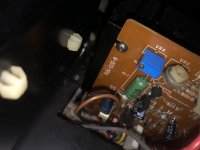
At this point I was frustrated and since nothing was showing itself to have obviously failed, I just decided to take it off the bulb limiter and hopefully coax a more obviously failure out of it to help me trouble shoot what's going on. And fail it did! As soon as the relay clicked the first time, there was a massive flash, pop and puff of smoke. Naturally, I shut the amp off. Now, I found that the body of TR22 had literally vaporized. TR12 also looks to be charred too but it could just be debris from the explosion of TR22. Thinking back I wish I had pulled the pre-main jumpers to at least isolate the problem but I forgot to so that variable is still up in the air. I tried putting it on the bulb limiter again and there's no dead short indicated. The protection relay "RL2" still cycles on and off. There are also individual relays on the power amp boards RL1, RL2 that switch between the class A and class B operating modes which are different than RL1 and RL2 on the power supply board and hopefully they didn't get damaged because they are a pretty funky looking, non standard relay.
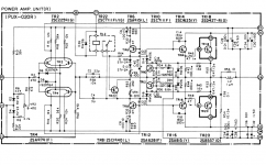
Anyways, I plan on taking the power amp card out again and replacing the burned transistors and replacing all the other transistors on the board except for the dual input FETs since there only seem to be ebay options left for those and they tested great and were well matched between sides when I tested them. Ill continue testing other components while I'm in there. While this circuit looks pretty simple, I'm a bit lost as to what exactly is going on, especially when it comes to assessing the failure mode. One initial thought I had when the I found the driver transistor TR16 shorted is that maybe the output cases are still somehow shorting to the heat sink even though I can't measure it but that maybe they do when under power. I suppose I should pull and test the outputs again anyways and this time replace the mica's since I ordered a bunch. If someone could help walk me through this circuit a bit and brainstorm what may have caused the latest failures, that would be much appreciated!
Schematics, manual, and pic of charred transistor and funky relay attached.
I have been working on restoring my Denon Pma 830 integrated amp and started to run into some problems after re-capping the Right channel power amp and phono preamp. Before that the amp seemed to work ok but didn't sound quite right to me which led me to the restoration efforts.
During that round of work, some of the wired connections between the board to the output transistors had unknowingly failed due being brittle and flexing but I think they were still touching the respective pin on the output transistor so it's hard to say what exactly what was going on there. That's the only mistake that I was able to find for that round of work. So when I hooked up the amp after that round of work, I initially powered it up on the light bulb limiter with no indication of a short and it came out of protection right on cue. I checked the DC offset and it was pretty high considering the amp was working fine previously before this round of work and that I had already set the offset to 0V. However, I figured that maybe the trimmer had gotten disturbed during the work and I had no problem re-setting it to 0V so I moved on to checking the bias. I started by trying to check the bias in class A mode and I got a low value on the R channel and I was only able to adjust it up to about 180 mV (spec is 0.5V) at which point I thought I caught a hint of the smell of an overheating component so I shut the amp off. I switched the amp into class B mode and tried measuring the bias and in class B mode, setting the bias was no problem and there was no more hot smell so I moved on to the left channel and did the same. I then tried to listen to some music and while there wasn't anything screaming out as an obvious problem I thought that it didn't sound totally right (kind of anemic and lower volume than I was used to at the same setting, especially in the right channel).
I then switched it back to class A mode and checked the bias on the left channel. It was basically right at .5V which is the spec in the service manual. I plugged the headphones back in and turned up the volume and after a couple seconds I heard a loud buzz and the music dropped out of the R channel and I immediately shut the amp down. Smoke started coming from the R power amp card. and I was able to trace it down to R48 (it was glowing red hot), the base resistor on the TR20 2SB577 output. Well, schucks! I went back and I hooked it up to the light bulb limiter and a dead short was now apparent it would not come out of protection at all.
I went in and pulled the outputs and they actually measured fine. I then found a bad driver TR16 (2SA815) and replaced it and its compliment,TR14 with MJE172 and MJE182 respectively. I have double checked the orientation of the transistors. While I was in there I replaced all the 1S2076A diodes with 1n4148. I also replaced D18, and D20 with 1n4007. r42, 44, 46, 48, 56 were also replaced. Many of the other components were measured including all transistors and remaining diodes with my atlas DCA. I reinstalled the outputs with new thermal paste, but I did not change the mica since they were stuck tight to the heat sink. I checked for shorts between the transistor case and heatsink and all looked good. I stripped back the wires and resoldered all connections between the output transistors and board. However, it looks like I will need to replace these wires outright as they are still brittle even after being stripped back and the flexing has caused many strands to break again already.
Anyways, I felt like I had done my due diligence so I reassembled everything and made an attempt to test it. I powered it up on the bulb limiter and there was no indication of a dead short and the relay clicked but it continued to click intermittently. I was able to zero out the dc offset during this time on the R channel but the relay continued cycling. At the same time I thought I saw some wisps of smoke rising but I'm not entirely sure as it could have been cat hair too (lol). But I did smell something like hot plastic so I powered the amp down. Well schucks, there's still a problem.
At this point I was frustrated and since nothing was showing itself to have obviously failed, I just decided to take it off the bulb limiter and hopefully coax a more obviously failure out of it to help me trouble shoot what's going on. And fail it did! As soon as the relay clicked the first time, there was a massive flash, pop and puff of smoke. Naturally, I shut the amp off. Now, I found that the body of TR22 had literally vaporized. TR12 also looks to be charred too but it could just be debris from the explosion of TR22. Thinking back I wish I had pulled the pre-main jumpers to at least isolate the problem but I forgot to so that variable is still up in the air. I tried putting it on the bulb limiter again and there's no dead short indicated. The protection relay "RL2" still cycles on and off. There are also individual relays on the power amp boards RL1, RL2 that switch between the class A and class B operating modes which are different than RL1 and RL2 on the power supply board and hopefully they didn't get damaged because they are a pretty funky looking, non standard relay.
Anyways, I plan on taking the power amp card out again and replacing the burned transistors and replacing all the other transistors on the board except for the dual input FETs since there only seem to be ebay options left for those and they tested great and were well matched between sides when I tested them. Ill continue testing other components while I'm in there. While this circuit looks pretty simple, I'm a bit lost as to what exactly is going on, especially when it comes to assessing the failure mode. One initial thought I had when the I found the driver transistor TR16 shorted is that maybe the output cases are still somehow shorting to the heat sink even though I can't measure it but that maybe they do when under power. I suppose I should pull and test the outputs again anyways and this time replace the mica's since I ordered a bunch. If someone could help walk me through this circuit a bit and brainstorm what may have caused the latest failures, that would be much appreciated!
Schematics, manual, and pic of charred transistor and funky relay attached.