Hi, I am about to build my first solid state build and first phono stage build. The schematic below is for the Boozhound Labs phono stage. I have 2 questions:
1. What is the purpose and recommended size for C6 and C7 capacitors? I was hoping to use some existing 30uF WIMA DC Link caps, but not sure if the uF is large enough for this purpose.
2. I plan on using a Lithium Iron Phosphate battery power supply for the 24V DC. This design consumes 30-50mA, so using a 2AH rechargeable battery pack should give ample listening time. But, most 24V battery packs have built in BMS (Battery Management Systems). I am concerned that the BMS' have some sort of unfavorable voltage filtering, regulation and/or regeneration that might negate the purpose of using the battery (pure DC). Any thoughts on this?
Any input would be appreciated.
Thanks!
Attachments
They are there for decoupling both stages themselves and fron supply. But you can ignore them if battery powered, it has rather low internal impedance.
Warning with those batts and charging/discharging methodology, they can catch fire.
Warning with those batts and charging/discharging methodology, they can catch fire.
BMS on LIFePO4 batteries activate when charging. If one stack of cells reaches cutoff voltage before the others, the BMS disconnects that stack and lets the charger work on the other stacks until all stacks reach the cutoff voltage and the charger shuts off. Don't use the phono board while charging.
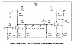
C5 C6 appear to be filter caps and 30 uf, 22 uf, 47 uf should probably all be fine.
Those film capacitors after the first transistor appear to be some sort of RIAA filter function. .33 uf parallel .1 uf is .43 uf which is not a value you can buy. The .01 uf series a resistor appears to be some sort of filter node. Precision caps will get you a more accurate curve.
No, those caps aren’t nearly big enough. Isolating two stages with resistors, and then using small decoupling caps INVITES motorboating. The pole frequency between the R and C needs to get down in the fractional - Hz so that the coupling cap between stages can set the dominant pole of the unintentional feedback loop through the drain supply. When the decoupling cap size is limited R has to be increased. Or make the coupling cap smaller, which reduces bass response or at least mess with the RIAA curve.

Following wg_ski's comments, the pole frequency = 1 / (2piRC). If R is increased to 17K and C = 33uF, then pole frequency = 0.28hz. Sufficient? I just want to ensure that changing R4 & R11 to 17K won't mess with the RIAA curve.
But a 17K resistor will drop too high valuable voltage from the FET's drain. Try it as is. If it fails, thus imagine all sort of alternatives to play with.
And will probably upset the RIAA response. As indianajo notes , the RC network is a filter, for the RIAA curve. The LF time constant is set by the combination of the 28k and 3.16k resistors and the first 100nF cap, with the series 3.16k flattening the response at around 500Hz, then the combo 33+1nF (34nF) rolling off after 2kHz.
It's a modest fit; I haven't examined it in any detail, but would not recommend changing anything unless it is to improve the accuracy of the RIAA response, but then only after measurements and checking if a better fit is possible. I'm not sure if such a simple circuit can be improved much.
It's a modest fit; I haven't examined it in any detail, but would not recommend changing anything unless it is to improve the accuracy of the RIAA response, but then only after measurements and checking if a better fit is possible. I'm not sure if such a simple circuit can be improved much.
I would use a regulated supply because any variations will come through as signal.
IMO, a linear regulated wall supply is a better option.
Ed
IMO, a linear regulated wall supply is a better option.
Ed
Or just use bigger caps - big enough to make the time constants between them and R6 and R7 long. This is one of those situations where some fancy film cap ISNT better than an electrolytic of the proper value.
A regulated supply feeding the whole works would work well too - its output impedance may be low enough that bypass caps aren’t needed other than to reduce higher frequency noise. One often thinks that batteries have a low enough impedance - but it varies with the state of charge and could bite you.
A regulated supply feeding the whole works would work well too - its output impedance may be low enough that bypass caps aren’t needed other than to reduce higher frequency noise. One often thinks that batteries have a low enough impedance - but it varies with the state of charge and could bite you.
wg_ski - "just use bigger caps". Are you referring to C6 and C7? If so, I have some electrolytic 220uF 35V available. Sound right? I will be using battery to supply the 24V.
Also, is the FET sensitive to location? I plan on have this a very tight, close circuit and only the battery near by. My guess is that the caps and resistors will not impact the FET.
Yes, C6 and 7. 220 uF may still not be big enough, unless you also increase R6 and7 to a couple hundred ohms. Increasing to a few k is probably not an option, but a few hundred is. If it motorboats, the time constant needs to be decreased - somehow. Eventually, the high pass filtering action of the DC block between stages will get it to stop, but only when it’s time constant is significanly smaller.
Location doesn’t mean much for low frequency. High frequency problems can crop up due to poor layouts but low frequency its pretty much just R and C.
Location doesn’t mean much for low frequency. High frequency problems can crop up due to poor layouts but low frequency its pretty much just R and C.
- Home
- Amplifiers
- Solid State
- Purpose and size of caps in Phono Stage